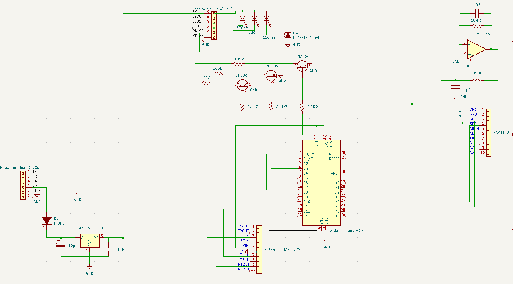
Regulates input power and ensures safe and reliable voltages for components.
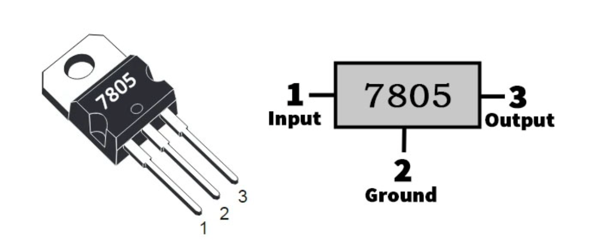
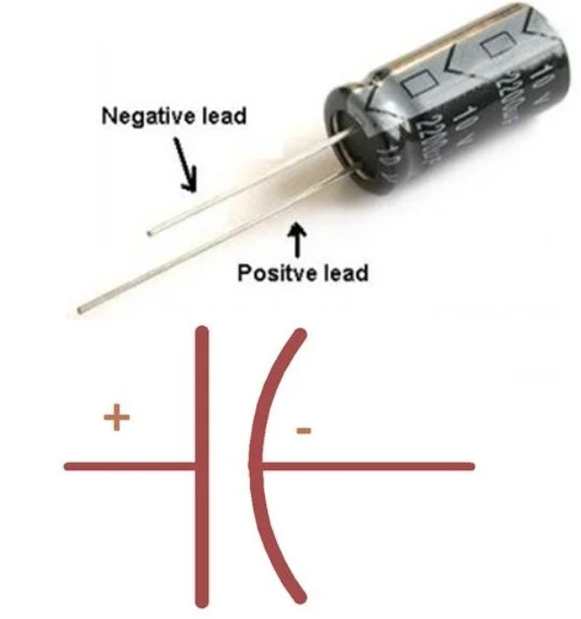
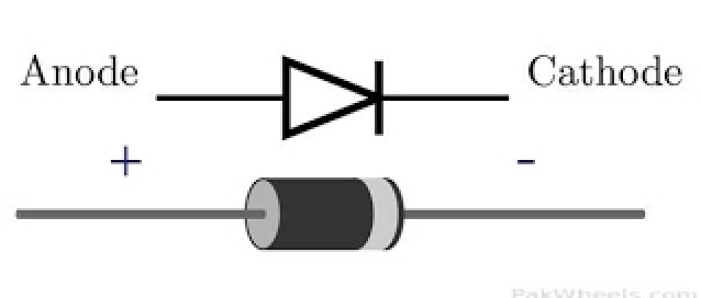
- ensure correct polarity of diode and 10µf capacitor.
| LM7805 Pinout | Capacitor polarity | Diode Polarity |
|---|---|---|
 |
 |
 |
Converts UART to RS232. Allows serial communication between sensor and computer. -Check RX and TX pins. T1out and R1in to the screw terminal. T1in and R1out to the Arduino.
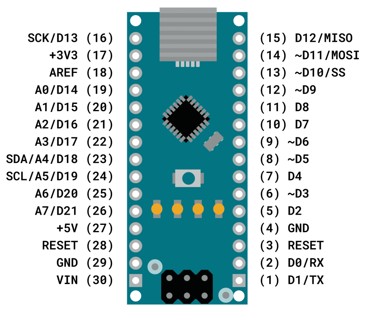
Microcontroller used to switch LEDs on and off as well as record and smooth data from the ADC. -Check RX, TX and Digital pins.
| Arduino Nano Pinout |
|---|
 |
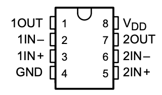 Transimpedance amplifier circuit to convert photodiode signal to voltage as well as amplify it before the ADC.
- 10MΩ and 22pf in parallel between 1in- and 1inOUT. PD cathode connects to 1in-. 1OUT goes to the low pass filter. *Make sure OpAmp is powered
Analog-Digital Converter. Converts the analog voltage signal from the photodiode amplifier to a digital signal readable by the Arduino. SDA transfers data and SCL transfers clock information. A0 channel is what I have been using. You could theoretically use any channel. Ensure the input to the channel comes from the low pass filter after the capacitor.
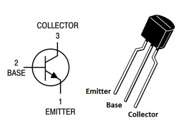 Transistors are used in common emitter configuration as switches to allow the Arduino to control the current to power the LEDs. Pin 1 to GND, pin 2 comes from Arduino with 5.1KΩ, resistor pin 3 comes from LED negative terminal with 100Ω resistors.