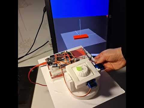
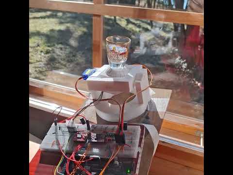
A gimbal suspended north pointing visor. It is a cardanic suspension build on a base plate, with two "rings" an outer ring, which is rotating around an axis , suspended on two bearings on the the perimeter of the ring at 180 degree. The rotation angle is controlled by an servo motor on one of the two bearings. Then in the inside of this ring there is another ring, which is also rotating, but the rotating axis is at 90 degree to the rotation axis of the outer ring. Also here the rotation angle is controlled by an servo motor on one of the two bearings. Then, in the inside of this inner ring is a motor, which can rotate freely, and it is has an encoder. On this motor axle, an round platform with an arrow (or a camera) is mounted. There is a electronic circuit, which is fixed on the base plate. So, when the base platform is mounted on a irregularly moving vehicle, gondola, vessel or airplane, the circuit is designed to control the two servo motors and the motor with encoder so that the arrow always stays horizontally, and the arrow (or camera) on the platform always points to the same direction, always compensating the movements of the airplane. This is commonly known as a "gimbal".
Circuit diagram

http://raikkulenz.kapsi.fi/downloadfolder_not_protected/stl.zip
http://raikkulenz.kapsi.fi/downloadfolder_not_protected/parts_stl.pdf
http://raikkulenz.kapsi.fi/downloadfolder_not_protected/NX-project-gimbal.ZIP
http://raikkulenz.kapsi.fi/downloadfolder_not_protected/kokonaiskuva.pdf

https://linktr.ee/Gyrovisor_gimbal
This circuit is designed to control a motor using an Arduino UNO, a TB6612FNG motor driver, and a motor with an encoder. The circuit also includes a logic level converter, a BNO055 sensor, and a PWM servo breakout board to control servos. The Arduino UNO reads the encoder values to control the motor's position using a proportional control algorithm. The circuit is powered via a USB C connection.
- TB6612FNG Motor Driver
- Description: Motor driver for controlling DC motors.
- Pins: GND, B01, B02, A02, A01, VCC, VM, PWMB, BI2, BI1, STBY, AI1, AI2, PWMA
- Motor N20 with Encoder
- Description: DC motor with integrated encoder for feedback.
- Pins: Red (Motor Power +), Black (Coding Power supply +), Yellow (Hall signal A), Green (Hall signal B), Blue (Hall sensor power -), White (Motor Power -)
- USB C to 2 Wires
- Description: Power supply interface.
- Pins: USB C, +, -
- Resistor (100k Ohms)
- Description: Passive component for current limiting or voltage division.
- Pins: pin1, pin2
- Resistor (33k Ohms)
- Description: Passive component for current limiting or voltage division.
- Pins: pin1, pin2
- Logic Level Converter
- Description: Converts voltage levels between different components.
- Pins: HV1, HV2, HV, GND, HV3, HV4, LV1, LV2, LV, LV3, LV4
- Micro Servo 9G (x2)
- Description: Small servo motor for precise control.
- Pins: GND, +5V, PWM
- Arduino Due
- Description: Microcontroller board for controlling the circuit.
- Pins: A0-A11, DAC0, DAC1, CANRX, CANTX, D0-D53, IOREF, MASTER-RESET, 5V, GND, VIN, AREF, SDA1, SCL1, MISO, Vcc, MOSI, SCK, Reset
- BNO085
- Description: Inertial Measurement Unit (IMU) for motion sensing.
- Pins: VCC, GND, SCL/SCK/RX, SDA/MISO/TX, ADR/MOSI, CS, INT, RST, PS1, PS0
- Electrolytic Capacitor (0.1 µF) (x2)
- Description: Capacitor for filtering and smoothing voltage.
- Pins: -, +
- Ceramic Capacitor (0.1 µF) (x2)
- Description: Capacitor for filtering and decoupling.
- Pins: pin0, pin1
- VCC: Connected to Arduino Due 5V, Logic Level Converter HV, and other components.
- GND: Connected to Arduino Due GND, Logic Level Converter GND, and USB C -.
- STBY: Connected to Arduino Due D9 PWM.
- PWMA: Connected to Arduino Due D5 PWM.
- AI1: Connected to Arduino Due D10 PWM/SS0.
- AI2: Connected to Arduino Due D4 PWM/SS1.
- A01: Connected to Motor N20 White (Motor Power -).
- A02: Connected to Motor N20 Red (Motor Power +).
- VM: Connected to USB C + and Resistor (100k Ohms) pin1.
- Red (Motor Power +): Connected to TB6612FNG Motor Driver A02.
- White (Motor Power -): Connected to TB6612FNG Motor Driver A01.
- Black (Coding Power supply +): Connected to Arduino Due IOREF, Logic Level Converter LV, and BNO085 VCC.
- Blue (Hall sensor power -): Connected to Arduino Due GND, Logic Level Converter GND.
- Yellow (Hall signal A): Connected to Arduino Due D2 PWM.
- Green (Hall signal B): Connected to Arduino Due D3 PWM.
- +: Connected to TB6612FNG Motor Driver VM and Resistor (100k Ohms) pin1.
- -: Connected to TB6612FNG Motor Driver GND.
- 100k Ohms: pin1 connected to USB C + and TB6612FNG Motor Driver VM; pin2 connected to Resistor (33k Ohms) pin2 and other components.
- 33k Ohms: pin1 connected to Arduino Due A1; pin2 connected to Resistor (100k Ohms) pin2 and other components.
- HV: Connected to Arduino Due 5V and other components.
- GND: Connected to Arduino Due GND and other components.
- LV: Connected to Arduino Due IOREF, BNO085 VCC, and Motor N20 Black (Coding Power supply +).
- HV2: Connected to Arduino Due A5.
- HV4: Connected to Arduino Due A4.
- LV2: Connected to BNO085 SCL/SCK/RX.
- LV4: Connected to BNO085 SDA/MISO/TX.
- +5V: Connected to Arduino Due 5V and other components.
- GND: Connected to Arduino Due GND and other components.
- PWM: First servo connected to Arduino Due D6 PWM; second servo connected to Arduino Due D7 PWM.
- 5V: Connected to TB6612FNG Motor Driver VCC, Logic Level Converter HV, and other components.
- GND: Connected to TB6612FNG Motor Driver GND, Logic Level Converter GND, and other components.
- D9 PWM: Connected to TB6612FNG Motor Driver STBY.
- D5 PWM: Connected to TB6612FNG Motor Driver PWMA.
- D4 PWM/SS1: Connected to TB6612FNG Motor Driver AI2.
- D10 PWM/SS0: Connected to TB6612FNG Motor Driver AI1.
- D2 PWM: Connected to Motor N20 Yellow (Hall signal A).
- D3 PWM: Connected to Motor N20 Green (Hall signal B).
- D6 PWM: Connected to first Micro Servo 9G PWM.
- D7 PWM: Connected to second Micro Servo 9G PWM.
- A1: Connected to Resistor (33k Ohms) pin1.
- A4: Connected to Logic Level Converter HV4.
- A5: Connected to Logic Level Converter HV2.
- IOREF: Connected to Logic Level Converter LV, BNO085 VCC, and Motor N20 Black (Coding Power supply +).
- VCC: Connected to Arduino Due IOREF, Logic Level Converter LV, and Motor N20 Black (Coding Power supply +).
- GND: Connected to Logic Level Converter GND.
- SCL/SCK/RX: Connected to Logic Level Converter LV2.
- SDA/MISO/TX: Connected to Logic Level Converter LV4.
- Electrolytic Capacitor (0.1 µF): Positive pins connected to Arduino Due 5V and other components; negative pins connected to Arduino Due GND and other components.
- Ceramic Capacitor (0.1 µF): pin0 connected to Arduino Due 5V and other components; pin1 connected to Arduino Due GND and other components.
The Arduino Due is programmed to control the motor driver, read encoder feedback, and manage the servos and sensor data. The logic level converter ensures proper voltage levels between the Arduino and the BNO085 sensor. The code integrates motor positioning, servo actuation, and orientation sensing into a single real‑time control loop. The Compass class handles all orientation processing from the BNO085. Incoming quaternion data from various SH2 sensor report types (Rotation Vector, Game Rotation Vector, and Gyro‑Integrated Rotation Vector) is converted into Euler angles using quaternion mathematics. The class updates yaw, pitch, and roll values and provides convenience functions for computing heading relative to magnetic north. The conversion logic uses trigonometric functions to derive Euler angles and supports both radians and degrees. In the main program, the Arduino Due initializes the motor driver (TB6612FNG) and monitors its supply voltage through a resistor divider. It reads the rotary encoder to track the motor’s current position and compares it with a continuously integrated heading that represents total rotation. A proportional controller converts position error into PWM output to drive the motor forwards or backwards. A dead‑zone prevents unnecessary oscillation when the motor is near its target. The BNO085 IMU is polled for new orientation data; when new sensor events arrive, the Compass class updates its internal state. Pitch and roll values are used to position two servos, allowing the system to physically reflect the sensor’s orientation. The loop runs continuously, coordinating motor control, orientation tracking, and servo movement to maintain synchronized and smooth operation.
sparkfun/SparkFun BNO08x Cortex Based IMU@^1.0.6 arduino-libraries/Servo@^1.3.0 paulstoffregen/Encoder@^1.4.4
The python program called protocoling_error.py was used to make a diagram of the error between target and measured encoder value.

Such a protocol can be used to optimize the PID parameters.
The python program called imu_visualizer.py was used to generate a stylized 3D model of the device on the screen to verify the correctness of the IMU sensor signals. You can see it in the YouTube demo video linked above. To do this, the currently commented-out command lines inside Compass.cpp (74-79), /* Serial.print("X: "); Serial.print(ypr_1.yaw); etc., must be enabled (i.e., the /* */ must be removed), and other Serial.print commands may need to be disabled.