feat(components): add diode variants and potentiometer/rheostat - #67
Conversation


Expand the standard library with the most-reached-for variable resistors
and diode-family parts (closes #25, closes #26).

#26 — Diode variants:
- ZenerDiode, SchottkyDiode, Photodiode, all reusing the Diode A/C
  terminals and anode/cathode roles.
- Refactor drawDiode into a shared drawDiodeBody helper; each variant adds a
  distinct cathode treatment (Zener lip bar, Schottky squared-S hooks,
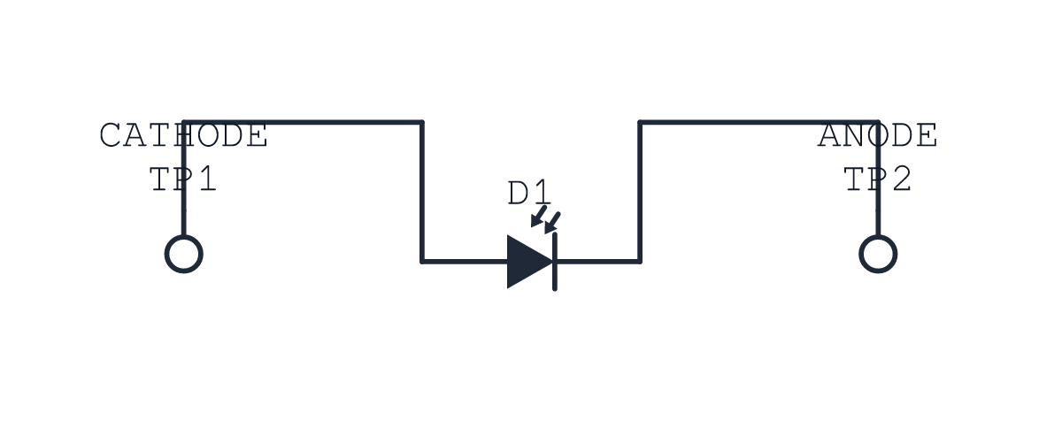
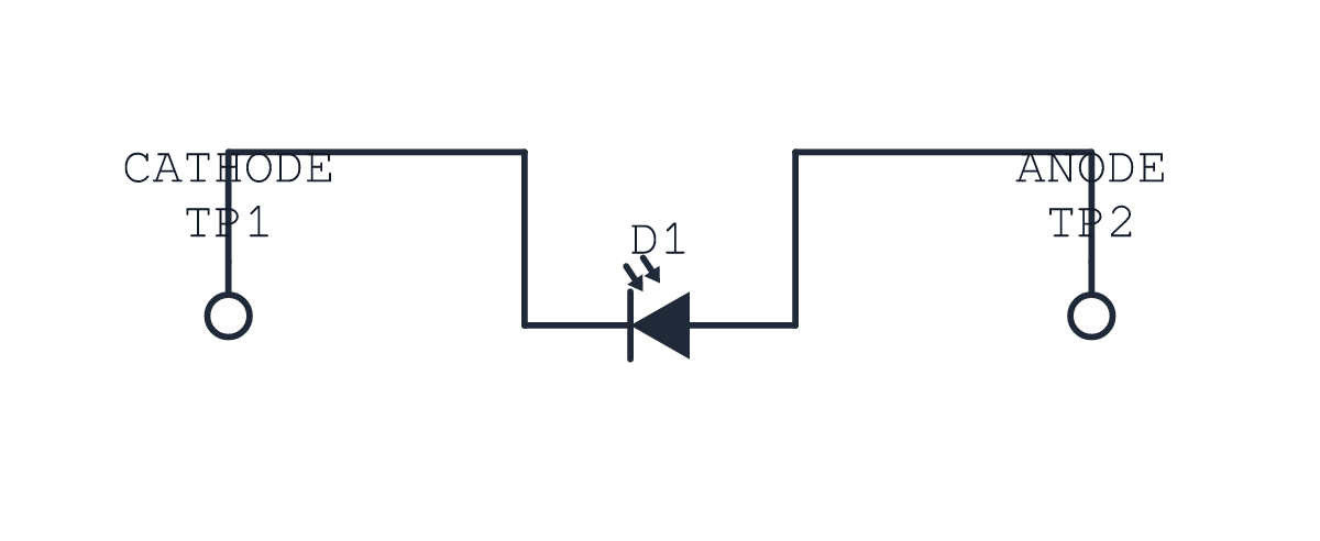
  Photodiode inward "incident light" arrows).

#25 — Potentiometer + Rheostat:
- Rheostat: two-terminal variable resistor (resistor body + diagonal arrow).
- Potentiometer: three-terminal (1, W, 2) with a wiper role. Adds a layout
  geometry branch placing the wiper as a perpendicular midpoint tap and an
  absolute-coordinate drawer, the same approach used for the transistor.
  The wiper auto-derives its side from position, so orientation hints rotate
  it correctly.

Tests: parts-catalog resolution for the new two-terminal parts, a
potentiometer block covering the wiper role and alias, and a snapshot.
Docs: MVP component table, CONTEXT wiper role, the authoring skill, plus two
new gallery examples (pot-divider, diode-variants).
The Zener used a non-standard bracket-shaped cathode bar (both ends bent
toward the anode) to avoid resembling the existing TVS mark. That reads as
wrong. Use the canonical Zener "Z" bar instead — top end bent toward the
anode, bottom toward the cathode. A unidirectional TVS shares this standard
mark by design; the bidirectional TVS remains the two-triangle form.

|
Fixed the Zener symbol after review. It was drawn with a non-standard bracket-shaped cathode bar (both ends bent toward the anode) to avoid resembling the existing TVS mark — but that just looked wrong. Now it uses the canonical Zener "Z" bar (top end bent toward the anode, bottom toward the cathode). A unidirectional TVS shares this standard mark by design; the bidirectional TVS stays the two-triangle form. Pushed as Re-checked the rest of the family against the standard symbols and the existing house style — all correct:
|
Audit visual verification
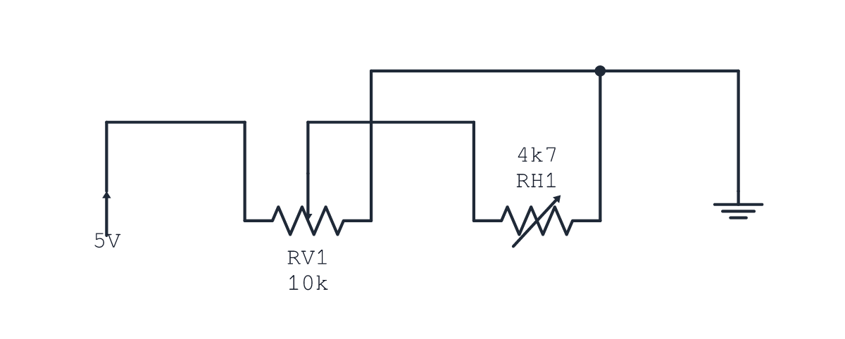
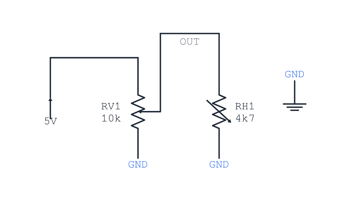
All images were produced from real Potentiometer divider — wiper contact and label clearanceBefore,
Vertical potentiometer — rotated label clearanceBefore, the labels overlap the upper terminal wire. After, the wiper, track, and labels rotate together with the labels clear of the connection.
Semantic diode roles — reversed local terminal declarationThe local component declares
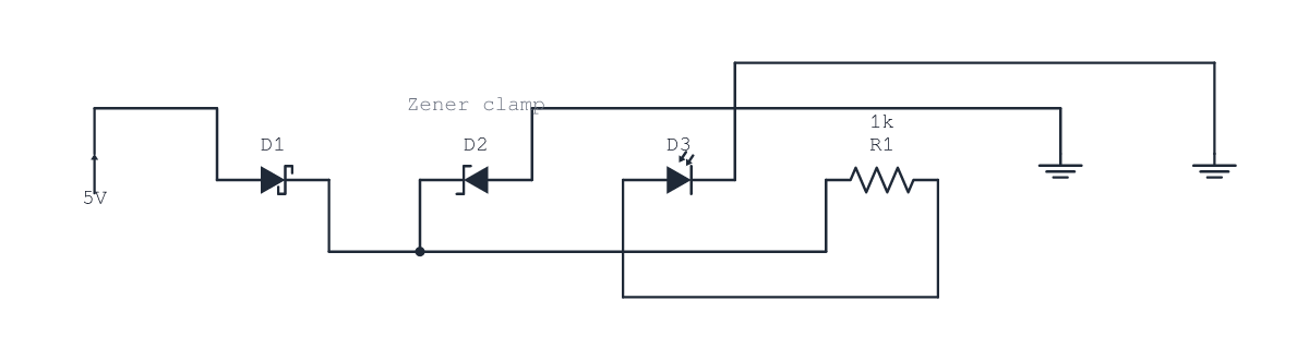
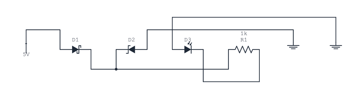
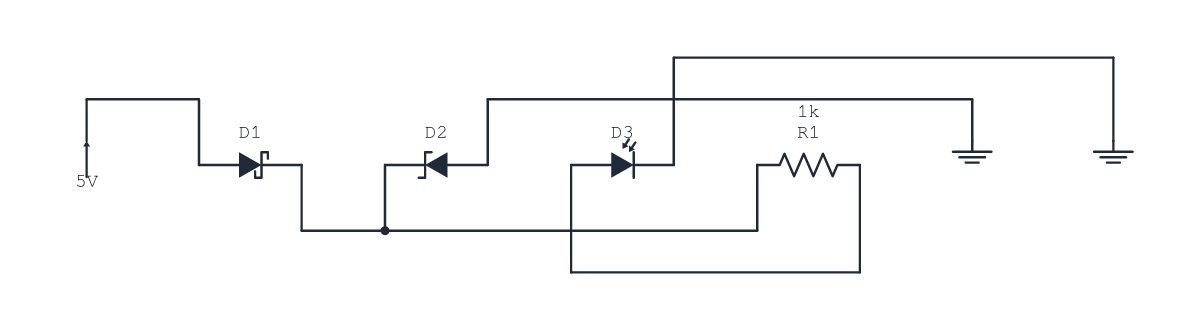
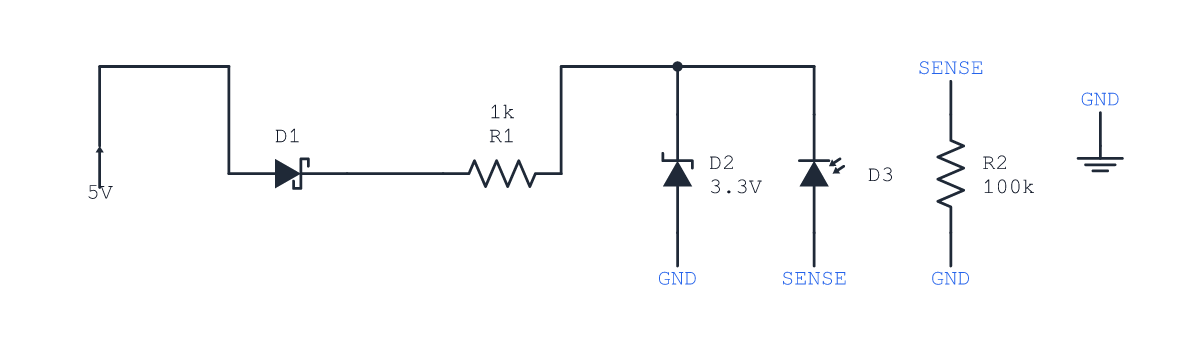
Diode-family example — polarity and annotation correctionThe submitted example forward-biased the photodiode despite describing a sensing leg, and the Zener annotation crossed a wire. After, the photodiode is reverse-biased and the obstructing annotation is removed.
|
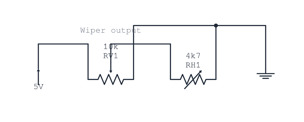
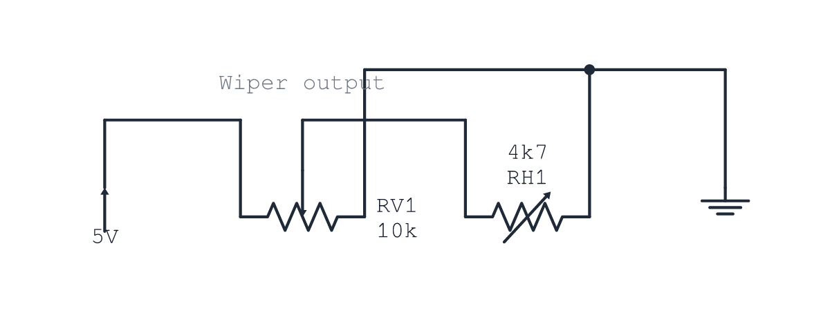
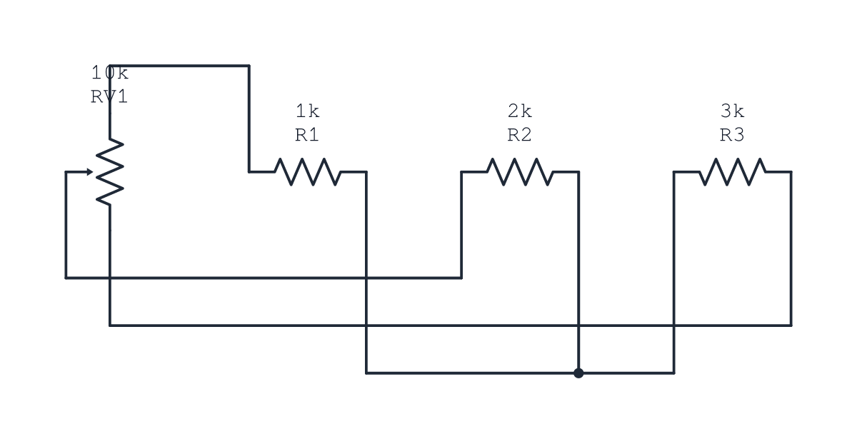
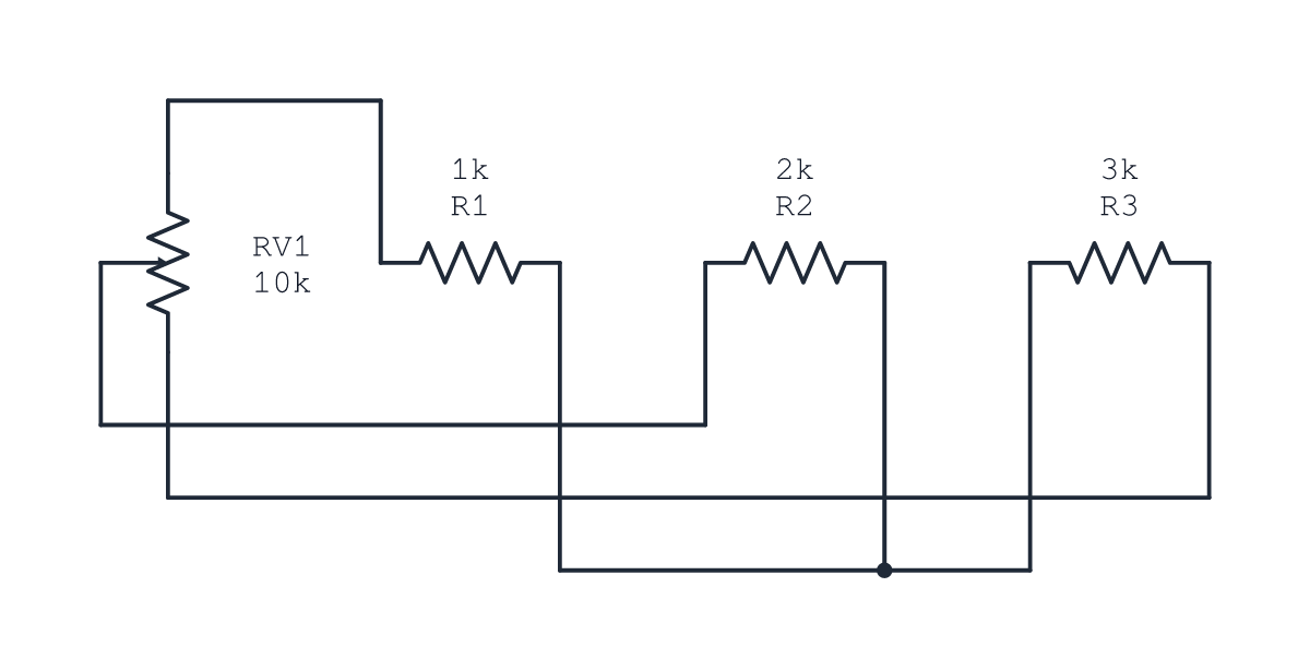
|
Implemented all five review fixes in
All 173 tests pass, along with typecheck, lint, docs formatting, and the full build. Both examples compile without diagnostics. Loaded potentiometer divider
Diode bias and sensing circuit
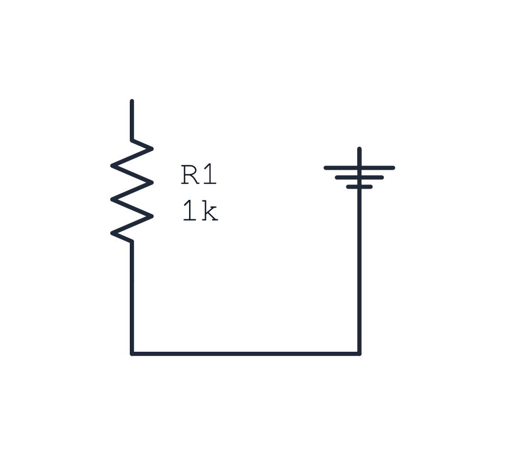
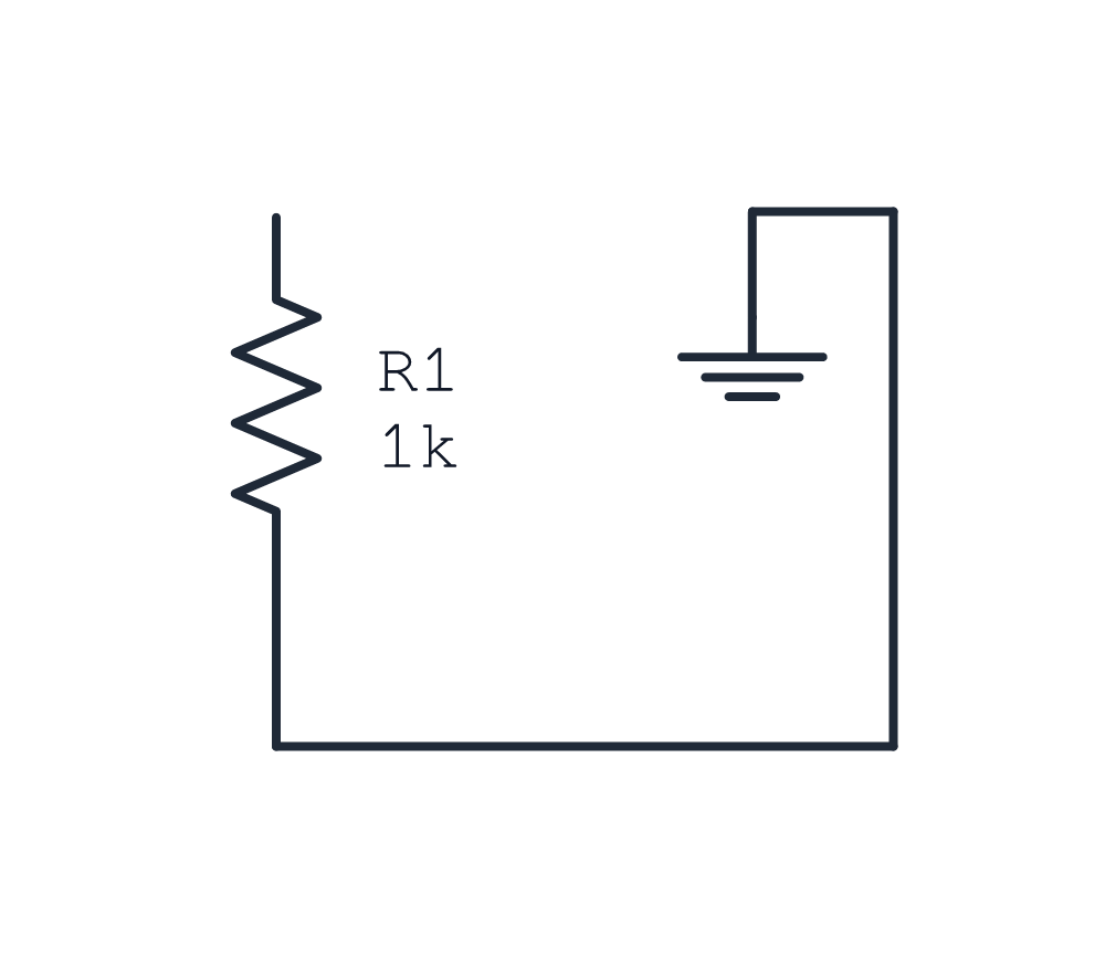
These two comparisons include the circuit source corrections. The previous examples are from PR commit Ground connection regressionSame source on main 0.3.1
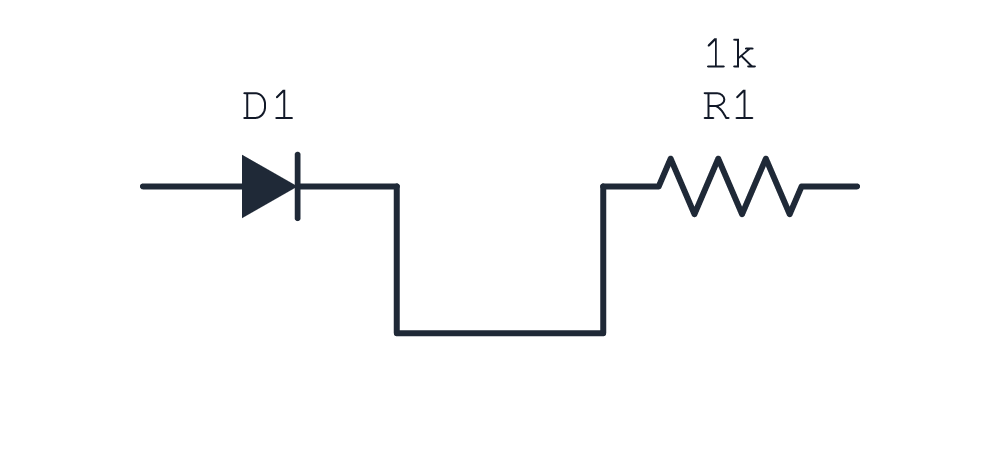
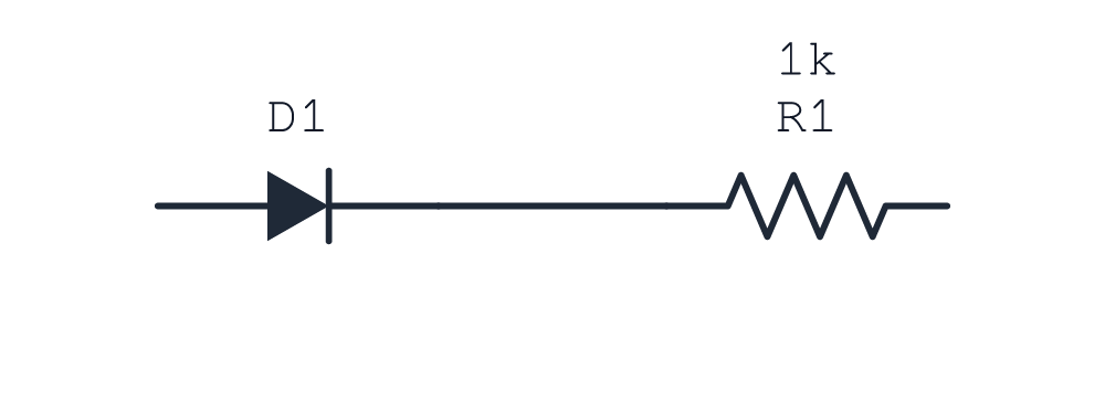
Direct connectionSame source on main 0.3.1 and the fixed branch. Adjacent facing terminals now connect directly.
All images were generated from actual |

1 participant

Summary
Adds
ZenerDiode,SchottkyDiode,Photodiode,Rheostat, and the three-terminalPotentiometerto the standard library, with catalog, authoring docs, and rendered gallery examples.Potentiometer labels sit opposite the wiper and its arrow touches the track. The layout can mirror the wiper toward its load. Vertical two-terminal branches use connection order and explicit power/ground references to choose their orientation in horizontal flows. Adjacent facing terminals connect directly, and lower-rail ground connections pass around the glyph rather than through its bars. Vertical optical component labels leave space for the light arrows.
The examples now describe coherent circuits:
voltage=3.3V, reverse-biases the photodiode, and connects its 100 kΩ sense resistor and Zener return to one explicit GND net.Closes #25
Closes #26
Validation
All 173 tests pass, plus typecheck, lint, docs formatting, and full build. Both examples pass the bundled CLI with zero diagnostics.
Regression checks cover the original potentiometer label/arrow issues across four directions and two orientations, outward ground-terminal approach, example net memberships, diode polarity, Zener voltage labels, direct connections, visible OUT, and absence of collinear overlaps and foreign-terminal hits in both examples.
Release 0.3.1 alone did not fix the reported discrete-component issues. These fixes are included here. General annotation collision avoidance is unchanged.
Render comparisons
Images and exact fixtures live on the throwaway
demo/pr-67-v031-assetsbranch underdocs/assets/pr-67-v031/realistic/, outside the feature branch. All images use the bundled SVG renderer and Resvg.The following unchanged sources compile on main. Main 0.3.1
94896abis on the left; this branch is on the right.Direct connection
Ground terminal approach
Vertical diode branch
The new types do not compile on main. These gallery comparisons show the prior PR examples at
d3a1828on the left and the corrected circuits on the right. They include the source edits described above.Loaded divider
Diode bias and sensing circuit
Investigation and fix report