Minimal Example El2004
A complete hardware + software walkthrough
The EL2004 LED Toggle Example is a minimal demonstration showing how to control digital outputs on a Beckhoff EL2004 EtherCAT terminal using the QiTech machine framework.
It represents the simplest possible hardware interaction in the system:
toggling LED outputs using the QiTech Control Dashboard.
- Beckhoff EL2004 EtherCAT Terminal (4-channel digital output)
- Beckhoff EK1100 EtherCAT Coupler
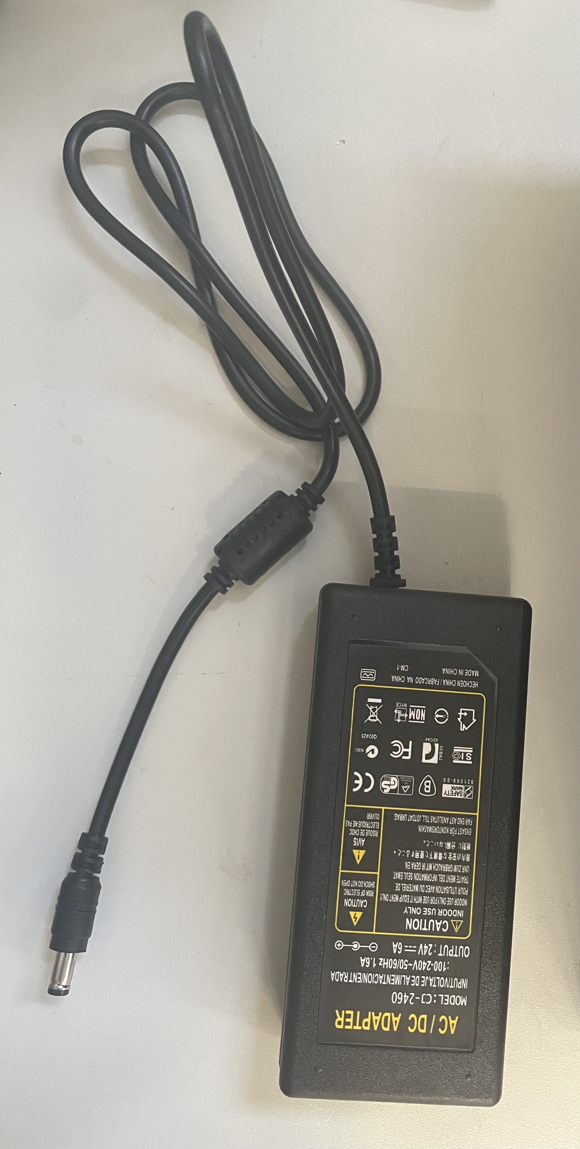
- 24 V DC power supply (AC/DC adapter + DC hollow plug)
- Jumper / bridge wires (0.5–1.5 mm² recommended)
- A Linux PC (Ubuntu/Debian recommended)
- Standard Ethernet cable
- Flat screwdriver
See Device Example Basics for software prerequisites.

This wiring configuration powers the EL2004 and prepares it for LED control.
It is not the only possible wiring but is the simplest functional setup.
⚠️ Always disconnect power before wiring. See Device Example Basics for the safe wiring procedure.
We supply power using a DC hollow-plug adapter, like this one:
https://www.amazon.de/dp/B093FTFZ8Q
Perform the following wiring on the EK1100:
- Red wire (+24 V) → Terminal 2
- Black wire (0 V) → Terminal 3
- Jumper wire from Terminal 1 → Terminal 6
- Jumper wire from Terminal 5 → Terminal 7
After wiring, your module should look like Figure 1.

Slide the EL2004 onto the right side of the EK1100 until it locks.
The EtherCAT E-Bus and power contacts connect automatically — no wiring required.


Connect the 24 V adapter to the hollow plug used earlier. Example AC/DC Adapter (Figure 4):
Use a standard LAN cable to connect your PC → EK1100. The final powered up and connected setup should look like this:

See Device Example Basics to install and run the software, then return here for the device-specific demo steps.
Once the backend + frontend are running, you should see:
-
EK1100 Coupler
-
EL2004 Digital Output Terminal

Steps:
-
Click Assign on the EK1100
-
Select TestMachine V1

- Enter a serial number (use the same for EK1100 + EL2004)

-
Click Write
-
Repeat for the EL2004
Navigate to:
Machines → TestMachine
 You will see this interface:

You can now toggle the four digital outputs of the EL2004.
This guide incorporates information from official Beckhoff documentation. All diagrams, product names, and figures belong to Beckhoff Automation GmbH & Co. KG and are used here solely for educational purposes.
Referenced Manuals
This tutorial is inspired by the clarity and educational quality of Beckhoff manuals. All wiring illustrations and hardware descriptions in this guide are provided for demonstration purposes only and do not replace official Beckhoff installation guidelines.