rtcTrigger is an ESP32-based controller for small self-powered audio systems that need to wake on schedule, simulate button presses, and remain configurable over BLE.
The project currently targets:
Seeed XIAO ESP32C3as the preferred hardwareDS3231RTC modules over I2C with alarm wake viaSQW/INT- two PhotoMOS relays for
PowerandModebutton simulation - a BLE web client and a native Capacitor app for Android/iPhone
The core use case is:
- wake at an exact RTC time
- hold the speaker power button
- wait for boot
- press mode once to switch away from Bluetooth
src/,include/: firmwareclient/web/: Web Bluetooth client for Chromeclient/app/: Capacitor mobile app for Android and iPhoneplatformio.ini: board environments and firmware build config
- daily speaker schedule
- one-shot speaker trigger
- fixed BLE wake times through RTC
- interval BLE wake fallback
- battery voltage monitoring
- app-level BLE PIN protection
- per-board BLE name derived from MAC address
- trigger telemetry:
- last event type
- last event timestamp
- speaker run counter
- ESP32 board
- DS3231 RTC module
- 2x PhotoMOS relay channels
- battery and regulator/power path appropriate for the board
Seeed XIAO ESP32C3
Also supported for testing:
esp32-c3-devkitm-1Adafruit QT Py ESP32-S3
Defined in platformio.ini:
esp32-c3-devkitm-1seeed_xiao_esp32c3adafruit_qtpy_esp32s3_nopsram
Build examples:
pio run -e seeed_xiao_esp32c3
pio run -e seeed_xiao_esp32c3 -t upload
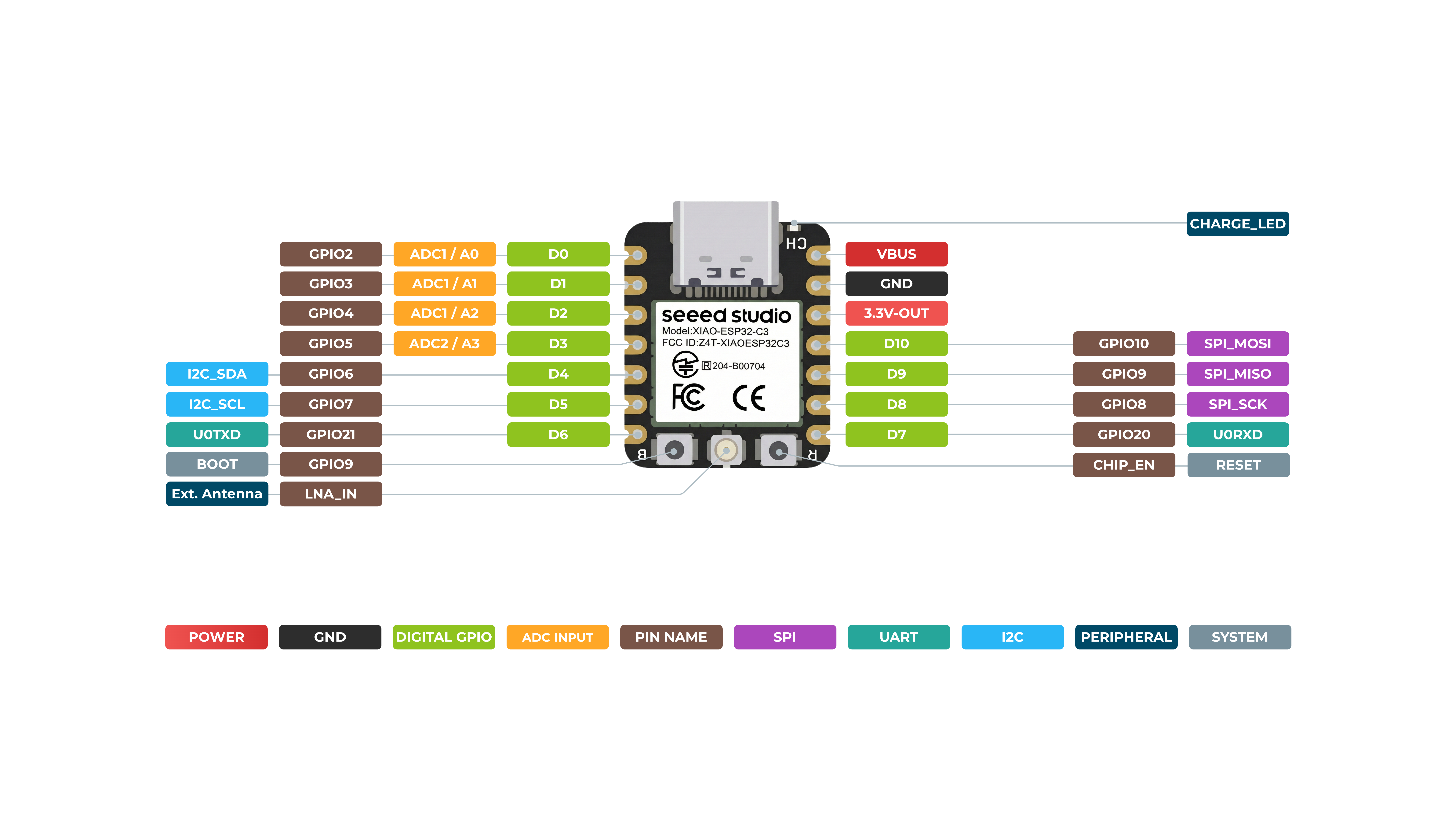
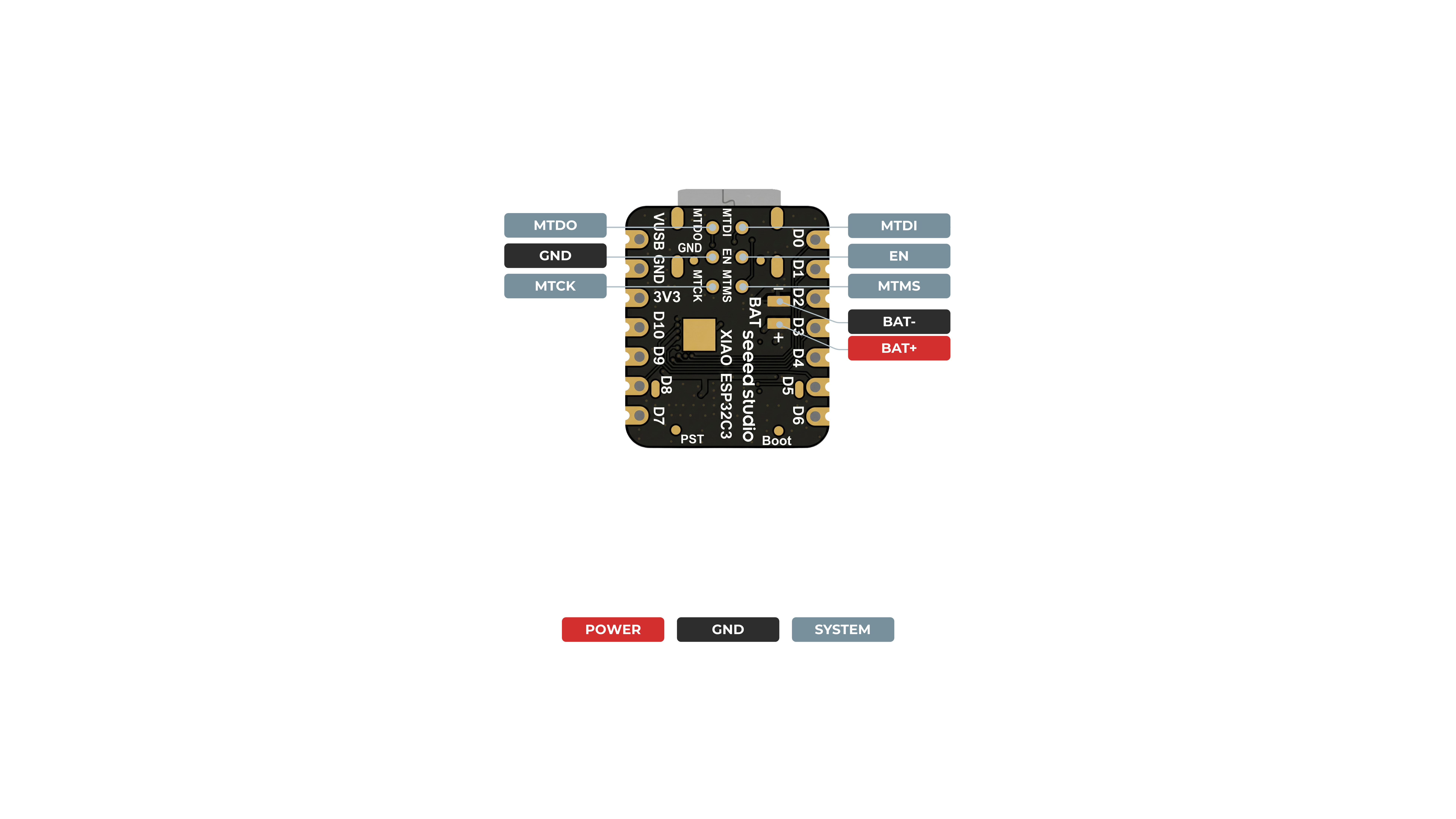
pio device monitor --baud 115200Official pinout references:
Front view:
Back view:
Pins used by this project on the XIAO:
D1 / A1 / GPIO3: Power relayD2 / A2 / GPIO4: Mode relayD3 / GPIO5: RTCSQW/INTD4 / GPIO6: I2CSDAD5 / GPIO7: I2CSCLD0 / A0 / GPIO2: battery ADCD7 / GPIO20: external status LED
Quick wiring table:
| Function | XIAO Pin | GPIO |
|---|---|---|
| Power relay | D1 / A1 |
GPIO3 |
| Mode relay | D2 / A2 |
GPIO4 |
| RTC interrupt | D3 |
GPIO5 |
| I2C SDA | D4 |
GPIO6 |
| I2C SCL | D5 |
GPIO7 |
| Battery ADC | D0 / A0 |
GPIO2 |
| Status LED | D7 |
GPIO20 |
GPIO3/D1/A1: Power relayGPIO4/D2/A2: Mode relayGPIO5/D3: RTCSQW/INTGPIO6/D4: I2CSDAGPIO7/D5: I2CSCLGPIO2/D0/A0: battery ADCGPIO20/D7: external status LEDGPIO0: recovery button / BOOT
GPIO18: Power relayGPIO17: Mode relayGPIO16: RTCSQW/INTGPIO41: I2CSDAGPIO40: I2CSCLGPIO9/A2: battery ADC
Use:
VCCGNDSDASCLSQW
Do not use:
32K
Notes:
SQW/INTis the alarm wake line- it is effectively open-drain, so a pull-up may be needed depending on the module
- on the current setup, a pull-up to
3.3VonSQWis acceptable if needed
Each relay input is driven from a GPIO through a series resistor.
Typical input wiring:
GPIO -> 220R to 470R -> PhotoMOS input+
GND  ----------------> PhotoMOS input-
Output side:
- wire across the existing button pads
- use one relay for
Power - use one relay for
Mode
The firmware expects a divider ratio of about 2:1 by default.
Typical divider:
Battery + ---- 100k ----+---- ADC pin
                        |
                       100k
                        |
Battery - --------------+---- GND
Default battery calibration:
divider x100 = 200empty = 3300 mVfull = 4200 mV
Supported trigger types:
- daily schedule
- one-shot
- direct BLE command
The current stable default timing is:
powerMs = 2200bootMs = 8000modeMs = 1000
Two BLE wake modes exist:
- interval wake
- controlled by
bleWakeSec
- controlled by
- fixed daily wake times
- controlled by
bleFixedWakeandbleWakeTimes
- controlled by
Example fixed BLE wake times:
09:00,13:00,17:00,19:00
Hold BOOT during reset/power-up to clear saved settings.
This restores defaults such as:
- PIN back to
123456 - schedules
- battery calibration
The firmware uses a plain-text command protocol.
Common commands:
TURN_ON_NOWPRESS_POWERPRESS_MODEGET_STATUSA 123456PIN 987654SCH 08:00ONE 2026-05-29T19:15CLEAR_ONESHOTRTC 2026-05-29T19:15SET_TIMING 2200,8000,1000,10000,60BD 200BE 3300BF 4200
Fixed BLE wake is sent internally in a compact form, but in the UI you enter normal times like:
09:00,13:00,17:00,19:00
The live status includes:
- auth state
- one-shot state
- BLE wake mode and times
- battery percentage and voltage
- RTC time
- next trigger
- last event
- last event timestamp
- speaker run counter
Useful trigger verification fields:
lastEventlastEventAtspeakerRuns
These are intended to let you verify scheduled execution even without a speaker connected.
Location:
client/web
Supports:
- Chrome on macOS
- Chrome on Android
Local run example:
cd client/web
python3 -m http.server 8080
Then open:
http://localhost:8080/client/web/
Notes:
- Android Chrome generally needs HTTPS for Web Bluetooth on non-local origins
- iPhone Safari does not support Web Bluetooth
Location:
client/app
The app is built with Capacitor and uses native BLE instead of Web Bluetooth.
Use Node 22 in that folder:
cd client/app
nvm use
npm install
Build web assets:
npm run buildSync native projects:
npx cap sync android
npx cap sync ios
Open Android project:
npm run androidOpen iOS project:
npm run iosFor iOS always use:
App.xcworkspace
not:
App.xcodeproj
This project is intended to be tracked in git from the repository root.
Generated artifacts are ignored, including:
.pio/node_modules/- Android build products
- iOS Pods/build products
At the time of this README rewrite, the following are working:
- RTC wake on
Seeed XIAO ESP32C3 - one-shot triggers
- fixed BLE wake times
- BLE connection and PIN auth
- battery readout
- trigger telemetry persistence
- external status LED on
D7 / GPIO20
- If you want to change pin assignments, start with
include/settings.h - If you want to change the status LED pin on XIAO, edit
src/status_led.cpp