
Infared Remote Control for a Light on my Fish Tank running ESPHome connected to Home Assistant
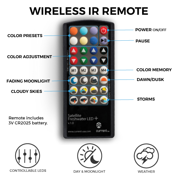
On my fish tank I have an LED light bar that can be controlled by an IR remote, specifficaly the Satellite Freshwater LED+ tank light. But it has no timer or other way to automate turning in on or off. It also lacks any ability to automate activating any of the many preset color modes. This meant I had the thing on a wifi connected switch that set up a timer to just turn it on and off, but I was really throwing away all to the other features, and it felt like a waste. I decided to build an "IR Blaster" that could be controlled using Home Assistant to set up timers, automations and other integrations with it.
I based my work of this great guide from David Sword who explains how to build an Infared Reciever to capture (learn) the IR Commands of a remote control, and then builds an Infared Transmitter to emulate the remote and replay those captured commands, and it was a HUGE help to getting this rolling.
While his project can effectivly create a "smart ir remote", one shortfall is that there was no awareness of the expected on/off state of the light. The device can only send the IR commands and had no way to track or inquire what the light was doing. This is made worse by the fact that this IR Light does not have dedicated for ON and OFF, and there was just one POWER button that acted like a toggle. So if I wanted to turn a light OFF, I would have to know if the light was actually ON before sending the IR command, or I might inadvertently turn the light ON when sending the Power (toggle) command. This probably could have ben addressed using Automations and Helpers in Home Assistant, but I wanted the state to be managed by the controller itself, so I had some work to do.
Some key features of my "IRLight Controller" include:
- Acts as an IR Receiver to Learn IR Commands of a Remote
- Acts as an IR Transmitter to send IR Commans like a Remote
- Uses a Virtual Power Switch to control and track the On/Off state of the Light
- Syncs the on/off state of the Built-In LED with the switch (configurable)
- Added a Physical Power Button to toggle the virtual Switch
- Includes all 32 buttons of the IR Controller (you can capture/name your own)
- Added Select component to put the most interesting buttons in a Drop Down menu
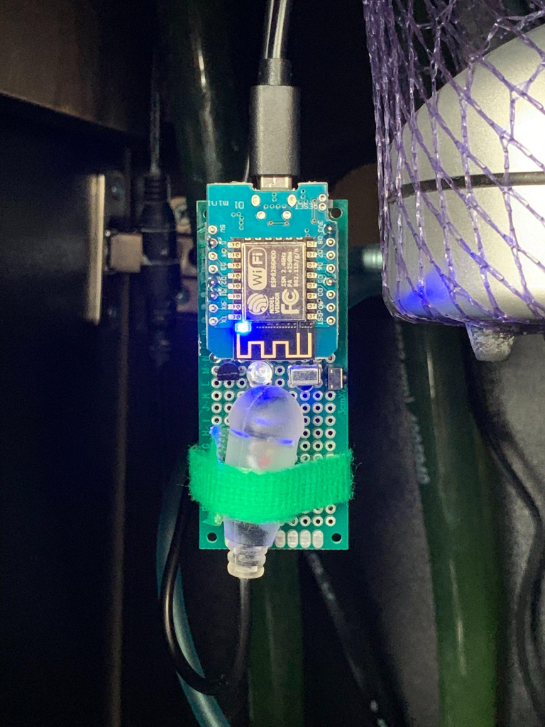
I'm going to assume you already are familiar with ESPHome and that you are probably using it with Home Assistant. When I wrote this I was using ESPHome v2022.1.2 and Home Assistant 7.1, which is already outdated, so I'm not going to cover setting all of that up. But even if you are not using Home Assistant, you can program your D1 Mini by connecting it via USB to your computer and then use https://web.esphome.io/ to write the firmware / configuration directly to the device over serial. It's amazing.
I built it using a D1 Mini, but other variants of an ESP8266 or ESP32 should would work fine if you manage the GPIO connections correctly. I also soldered all my parts to a prototying board, but to get stated I had everything in a mini bradboard, which could have easily been it's final home too if you don't want to solder anything (mine was in the bradboard for a few weeks while testing).
If you're just getting started, here are the kits I used. They include a lot more than you really need, so you could make several of these, or eventually make other things.
- $17 WeMos D1 Mini ESP8266 (pack of 5) - Need just one, but more are fun to experiment with
- $6 IR Receiver and Transmitters (pack of 10 each) - Need just one receiver and one transmitter
- $7 Transistor Kit (pack of 200!!) - Need just one of the BC337 NPN Transistors, to lots of extras
- $12 Small 400 Point Solderless Breadboard (pack of 6) - Need just one to connect everything
- $7 40pin Breadboard Jumper Wires (pack of 120) - Need maybe a dozen or less, depending on how you roll
- $12 PCB Prototype boards (pack of 32) - Need just one of the 3cm x 7cm boards if you solder the final build
Of course you also need a Mini USB cable and power supply, but most of us have those lying around these days. If you have to buy everything, you'd be looking at about $50, but if you left the whole thing in the bradboard an individual controller is less than $7. If you're like me and had most fo these things from a previous project, it might not really cost you anything new out of pocket.
After building this I also learned that there is an "IR Shield" available for the D1 mini that could make things even easier. I haven't used it so I don't know exactly how to connect and control it, but it's only $1.40+shipping, so it might be worth a look.
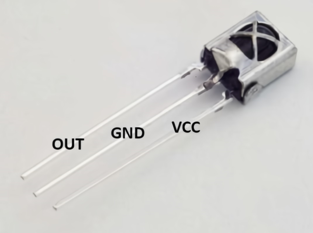
The IR kit I bought came with the VS1838B IR Receiver. It basically has it's own micro circuitry inside it so you need only to supply power and ground, then read the output on the output pin.
Connections
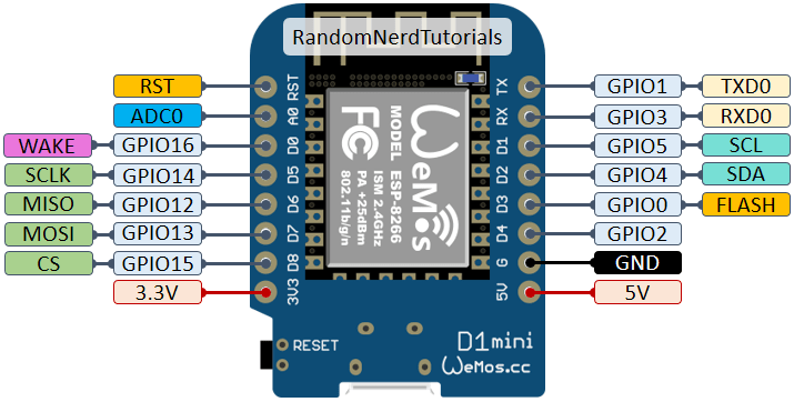
- GND to GND
- VCC to 3V3
- OUT to D5 (GPIO14)
remote_receiver:
  pin: #D5
    number: GPIO14
    inverted: True
    mode: INPUT_PULLUP
  dump: raw
  idle: 25ms
Once that's in place you can open the Log window of the device and capture all of the IR commands. Use David's blog as a guide for this step.
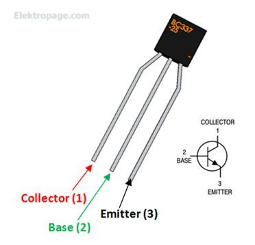
Now that we have the codes being transmitted by the remote, we want to replay those commands using the IR led. We do this with an IR LED and an NPN Transistor that'll manage the singalling. Specifically, we'll use a BC337 transistor, which has three pins.
PIN | Description Collector | Current flows in through collector, normally connected to load Base | Controls the biasing of transistor, Used to turn ON or OFF the transistor Emitter | Current Drains out through emitter, normally connected to ground
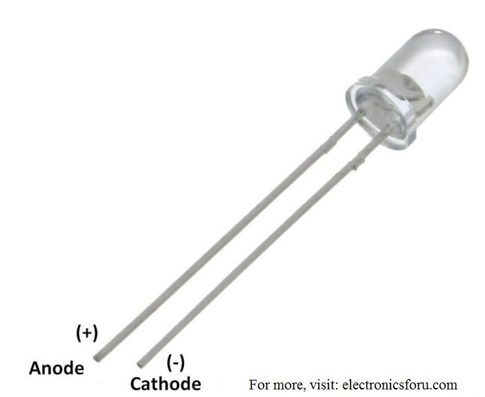
Connections
- Collector to GND
- Base to D2 (GPIO4)
- Emitter to Cathode (-)
- Anode (+) to 3V3
Then we need to add each of the buttons to the device to send the IR commands. Here's one example:
remote_transmitter:
  pin: #D2
    number: GPIO4
  carrier_duty_percent: 50%

button:
  # Power Toggle (ON/OFF)
  - platform: template
    name: "${devicename} Power Toggle"
    id: "irbtn_power"
    on_press: # Change the state of the Switch when pretting the Button
      - logger.log: "Button pressed (TOGGLE)"
      - turn_on_action:
        - remote_transmitter.transmit_raw:
            carrier_frequency: 38kHz
            code: [ 9014, -4447, 610, -516, 610, -516, 610, -516, 611, -517, 609, -517, 610, -516, 610, -516, 611, -516, 610, -1617, 610, -1618, 610, -1616, 611, -1618, 610, -1616, 611, -1616, 612, -1616, 611, -1617, 611, -1617, 610, -517, 609, -1616, 612, -1617, 611, -516, 610, -516, 611, -515, 611, -515, 611, -516, 611, -1616, 611, -516, 611, -516, 610, -1618, 610, -1616, 611, -1617, 611, -1616, 613]
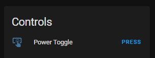
This would appear in Home Assistant like this
I also added physical button that can be used to toggle the power on/off because, why not!? This short video was a huge help on using a binary_sensor to wire up a simple button to a GPIO pin
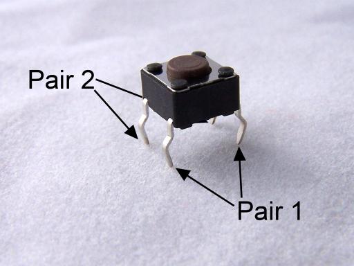
Connections One side of the button (Pair 1) to GND The other side of the button (Pair 2) D1 (GPIO5)
# A momentary press button that could be used to toggle the Power switch
# No resistor is necessary as we'll use the internal pullup setting for that
# Connect one pin to D1 (GPIO5)
# Connect the other pin to GND
binary_sensor:
  - platform: gpio
    id: gpiobutton
    name: "${devicename} Physical Button"
    pin: # D1 on the D1 mini
      number: GPIO5
      inverted: true
      mode:
        input: true
        pullup: true
    filters:
      - delayed_on: 10ms
    on_press:
      then:
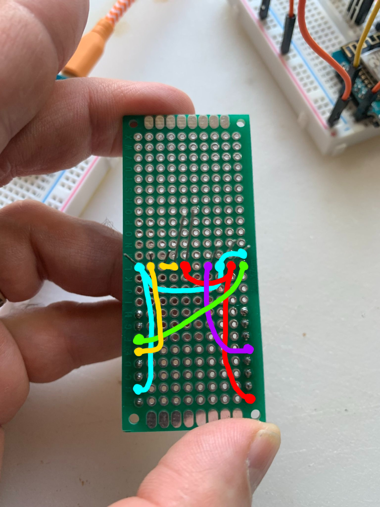
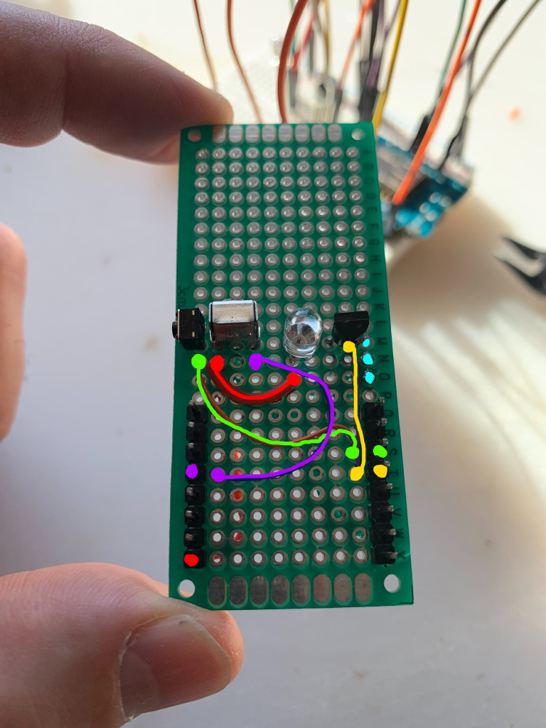
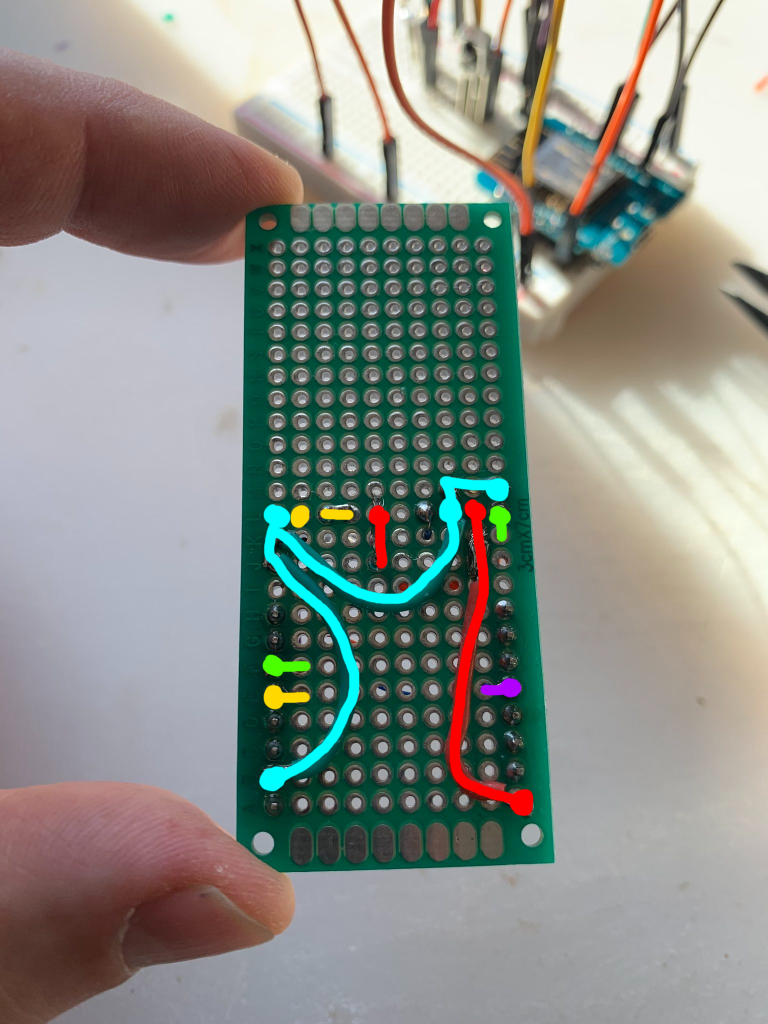
- button.press: irbtn_powerIf you don't want to leave the Bradboard permanently occubpied by this project, you can easily connect all of these to a prototypig board. I marked up a couple photos that helped layout part placement. I thought about making a custom PCB for it, but I suspect the IRShield for the W1 mini is probably a better place to spend the time and money at this point.
Here's the Top and Bottom of the board with a dry fitting of the parts and logical connection of the pins
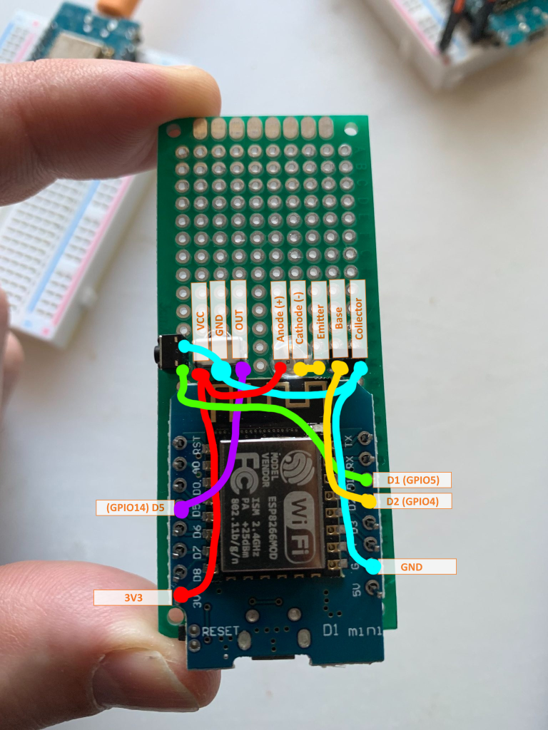
Here's the Top and Bottom of the board with the actual connection paths of the pins
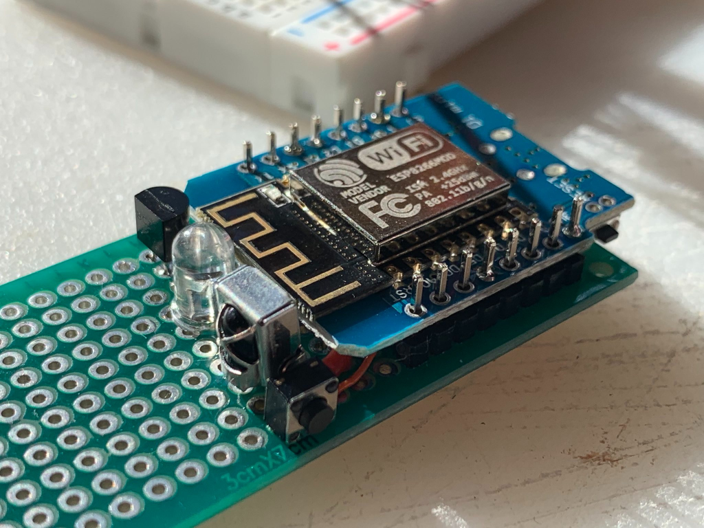
When it's all done, it should look something like this
The YAML configuration shown in the README here is just enough to test if the components are working, but it's not enough to make it useful. Sure you can capture IR codes and you can send an IR command, and you can even use the physical button to push the virtual button, but you really want to use the full configuration.yaml file to get all the other entities like buttons, switches and scripting that make this useful.
Kep in mind I am emulating this specific remote, but you can capture any remote and customize it to do whatever you need.
Here's the list of components that'll be come available for use with Home Assistnat.
