Detailed information about the design and construction of a flipdot display clock that retrieves time from a NTP (Network Time Protocol) server using an ESP32 wifi module.
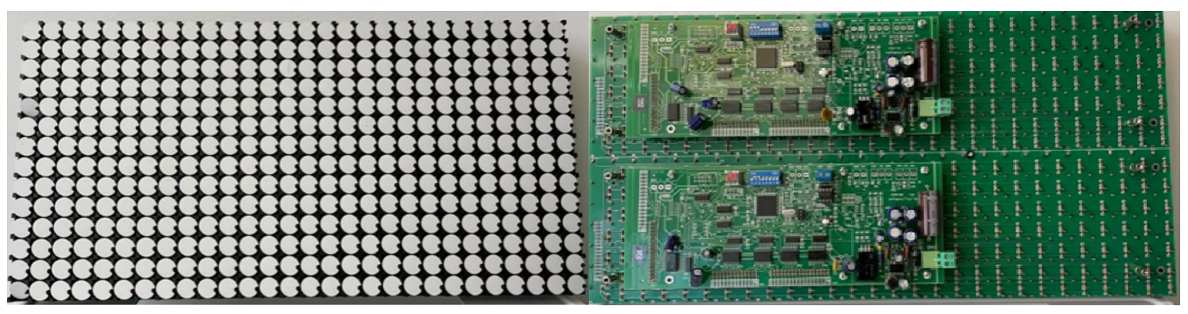
The flipdot display used is an Alfazeta XY5.
- Pixel size: 13.5mm (0.53")
- Supply voltage: 24 volts
- Resolution: 14x28
- Color: black (low) and white (high)
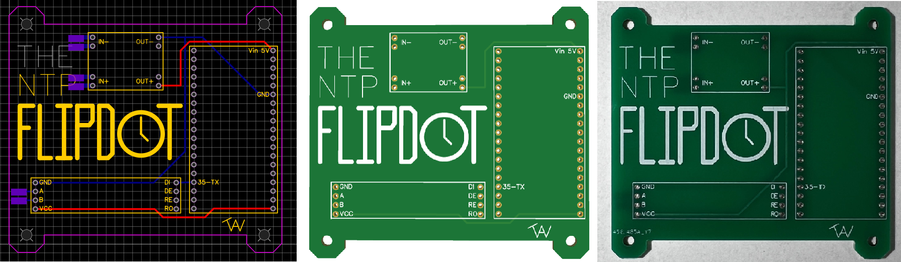
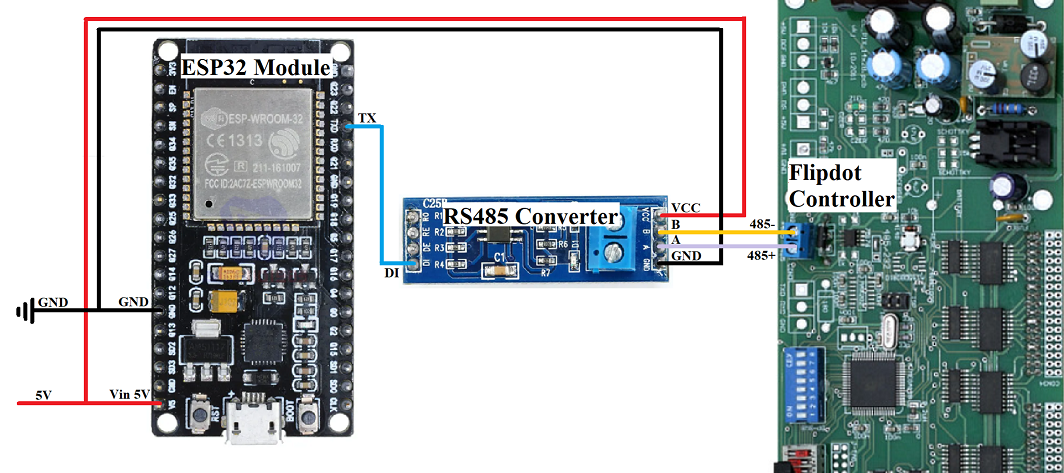
To make this project look as clean as possible, I designed my own simple PCB board that holds and connects the buck converter, ESP32 module, and RS485 converter.
- The CAD tool I use is EasyEDA which is simple and user friendly.
- When the design is completed, it can be exported and ordered through EasyEDA using JLCPCB.
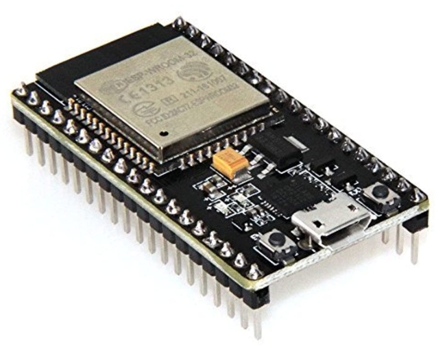
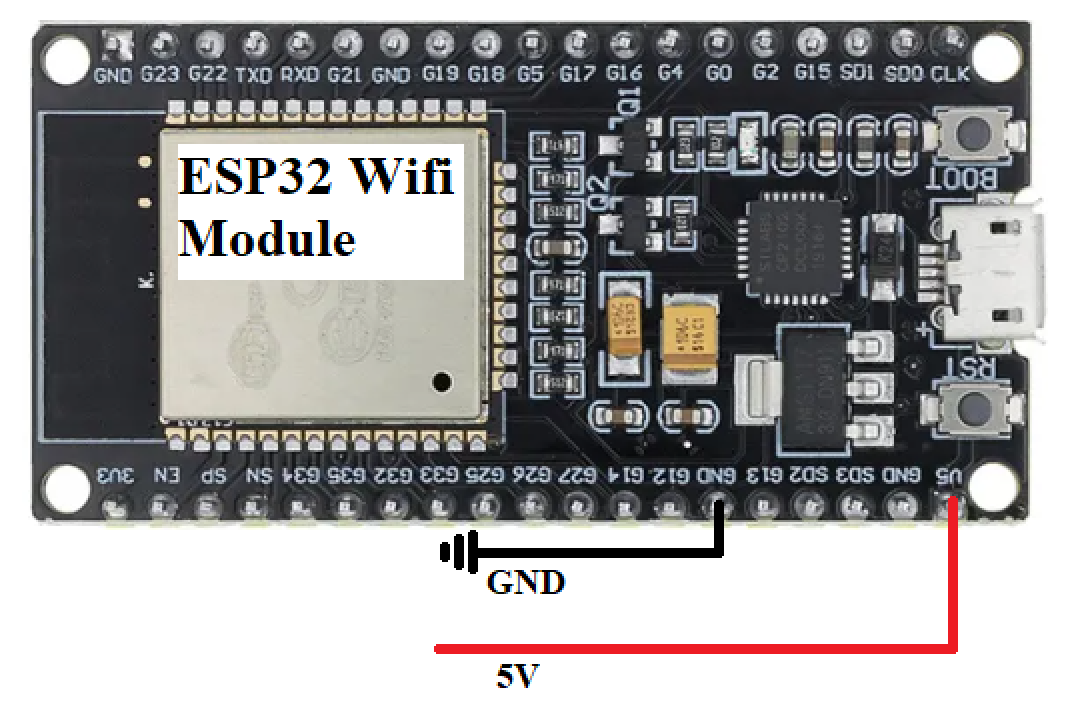
The wifi module used is a HiLetgo ESP-WROOM-32 ESP32 ESP-32S Development Board.
- This development board not only connects to wifi, but replaces the need for an Arduino Uno or equivalent additional microcontroller.
- When flashing code to the board, connect using micro usb and hold the flash button for ~2 seconds.
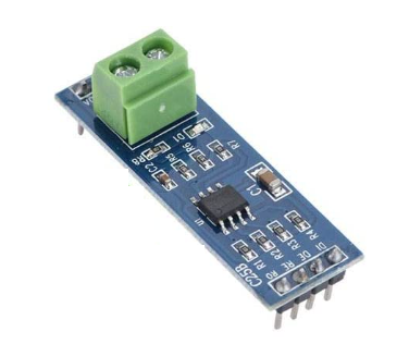
The RS485 converter used is a YWBL-WH TTL to RS-485 Converter Module.
- This module allows the microcontroller to output RS485 serial communication which is input into the flipdot controllers.
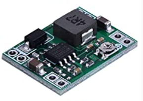
The buck converter used is a MP1584EN DC-DC Buck Converter Adjustable Power Supply Module
-
This buck converter takes in 24 volts and outputs 5 volts.
-
Ensure the output is adjusted to a value between 4.8 and 5 volts to ensure no components are damaged.
Note: If the converter makes high pitch acoustic noises when plugged in, try using a different 24 volt power supply as the consumption ratio may may not meet the converter requirements.
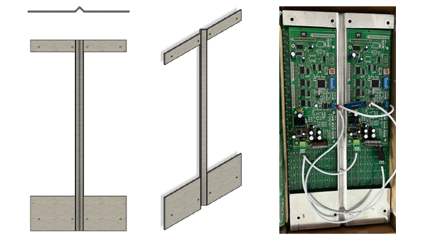
The flipdot display has standoffs but is mainly held together by a pcb board which is not ideal for the structural integrity of a vertical stand and case. To remove some of this stress I constructed a brace from a 13 gauge steel panel.
- the centerline of the plate is bent 90 degreed and -45 degrees on either end, doing this gives the brace strength in all 3 axis.
- cutouts were made to to fit onto the board standoffs and allow the pertruding controller board and external circuits to fit.
- 8 holes were drilled for the 8 accessible m3 board standoffs.
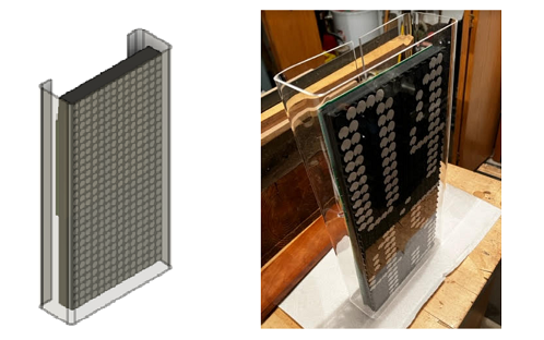
To make the four corner case:
- start with a sheet of plexiglass.
- cut the height of the plexiglass to the height of the body.
- use wood studs and clamps on either end of the plexiglass at the desired bending locations.
- using a heat gun, apply equal heat to bot sides at the crease near the wood.
- when plexiglass becomes pliable, use another wood stud to push the plexiglass to an angle of ~90 degrees.
- repeat process on other three corners.
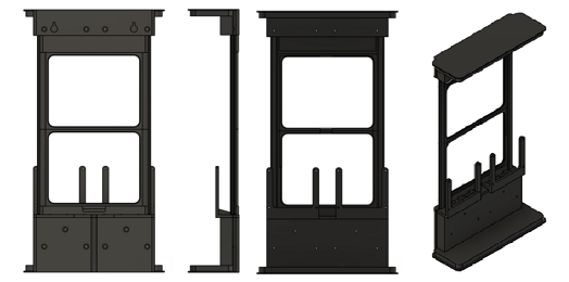
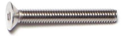
Screws were used to secure the flipdot display to the metal frame and 3D printed body.
- 2x M3 x 25mm
- 6x M3 x 40mm
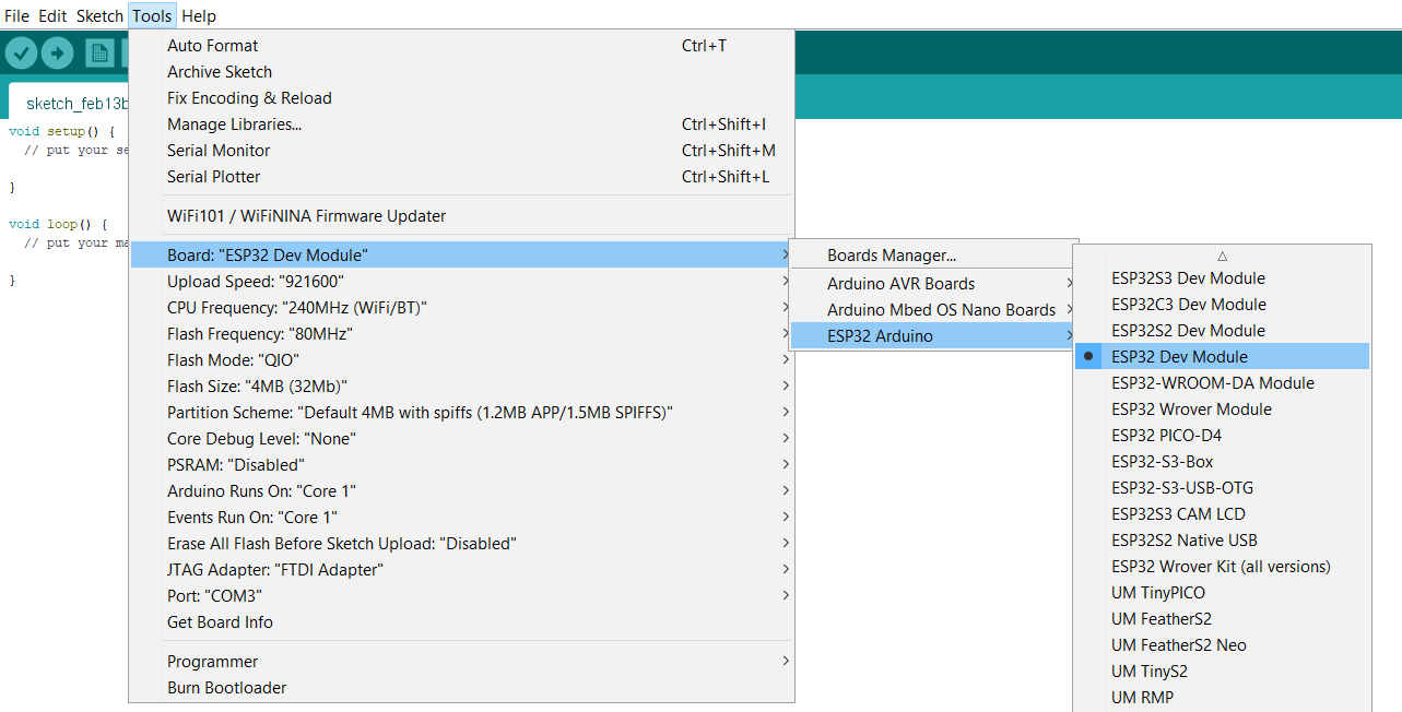
Programming was done in Arduino IDE. If using the esp32 module, follow these directions to add the board to the IDE.
When the board is installed, follow the picture below. Ensure the COM port matches where the devboard is plugged into the PC.
Below is an example of a data frame structure for a flip dot with ONE controller.
| Header | Command | Address | Display Data | End |
|---|---|---|---|---|
| 1 byte | 1 byte | 1 byte | 28 or 112 bytes | 1 byte |
| 0x80 | See Command | See Address | See Display Data | 0x8F |
Below is an example of a data frame structure for a flip dot with TWO controllers.
| Header | Command | Address | Display Data | Header | Command | Address | Display Data | End |
|---|---|---|---|---|---|---|---|---|
| 1 byte | 1 byte | 1 byte | 28 or 112 bytes | 1 byte | 1 byte | 1 byte | 28 or 112 bytes | 1 byte |
| 0x80 | See Command | See Address | See Display Data | 0x80 | See Command | See Address | See Display Data | 0x8F |
The purpose of the command byte is to let the controller know when to refresh the display. There are multiple different commands that can be used for various displays and system requirements. Pay attention to the # of data bytes for the command. 0x82 is a blank command that updates the display without a data byte number requirement. For example, a 14 by 28 pixel display with two controllers can use the 28 data byte command to update half of the display at a time or the 56 to update to entire display at once.
| Command in Hex | Command in Binary | # of Data Bytes | # of Controllers | Display Size | Refresh |
|---|---|---|---|---|---|
| 0x81 | B10000001 | 112 | One | Four 7x28 Displays | No |
| 0x82 | B10000010 | NA | NA | NA | Yes |
| 0x83 | B10000011 | 28 | Two | One 14x28 Display | Yes |
| 0x84 | B10000100 | 28 | Two | One 14x28 Display | No |
| 0x85 | B10000101 | 56 | Two | One 14x28 Display | Yes |
| 0x86 | B10000110 | 56 | Two | One 14x28 Display | No |
The address byte correlates to the different controllers and displays. Address byte values range anywhere from 0x00 to 0xFF in hex. In order for the display to work properly the DIP switch on the back of each controller must be set in binary to match desired address. For example, if the address DIP switch from 1-6 for one display is set to 011111 and the other display to 000001, the respective addresses are 0x1F and 0x01
Data is sent one byte (8 bits) at a time. Flipdot displays come in various shapes and sizes but all that I have come accross have rows that are split into groupings of 7. For example, my flipdot display is 14 by 28 pixels which is actually two displays put together (2x 7 by 28 pixels). The 7 pixels in each row are programmed by one byte. To program a 14 by 28 pixel display 56 (28*2) bytes of data are required. I find using binary numbers is best for the data programming in order to get a visual of the display while coding but hex will work as well. Since there are only 7 pixels to program but 8 bits in a byte, the most significant bit can be a 1 or a 0.
Below is an example of the flipdot output for a given byte.
| B7 | B6 | B5 | B4 | B3 | B2 | B1 | B0 |
|---|---|---|---|---|---|---|---|
| 0 or 1 | 1 | 1 | 0 | 1 | 1 | 1 | 0 |
| NA | White | White | Black | White | White | White | Black |
NTP stands for Network Time Protocol. The main purpose of NTP is to synchronize computer clock times through the network. The ESP32 wifi module is used to connect to a local network and request/receive time from the NTP. There are many different NTP clients that can be used, pool.ntp.org was used in this project due to it being free and reliable with ~4600 activer servers globally.
| Time Zone | Name | Hour Offset | gmtOffset_sec |
|---|---|---|---|
| HST | Hawaii Standard Time | -10 | -36000 |
| AKST | Alaska Standard Time | -9 | -32400 |
| PST | Pacific Standard Time | -8 | -28800 |
| MST | Mountain Standard Time | -7 | -25200 |
| CST | Central Standard Time | -6 | -21600 |
| EST | Eastern Standard Time | -5 | -18000 |
A time structure can be created using "struct tm" command. This structure contains the date and time broken down into integer variables.
Below is a list of commands that can be used with the time structure.
| tm Command | Type | tm Command | Type |
|---|---|---|---|
| tm_sec | int | seconds after the minute | 0-59* |
| tm_min | int | minutes after the hour | 0-59 |
| tm_hour | int | hours since midnight | 0-23 |
| tm_mday | int | day of the month | 1-31 |
| tm_mon | int | months since January | 0-11 |
| tm_year | int | years since 1900 | NA |
| tm_wday | int | days since Sunday | 0-6 |
| tm_yday | int | days since January 1 | 0-365 |
| tm_isdst | int | Daylight Saving Time flag | NA |
*Range is generally from 0-59 but can occasionally reach 61 to account for leap years.
/****************************************************************************
 *    Project: Flip Dot NTP Clock                                           *
 *    Written by: Tristan Weger                                             *
 *    Date: 05/20/2023                                                      *
 *    Description: The following code uses an ESP32 wifi module             *
 *      to connect to a NTP server to obtain local time and update          *
 *      a clock made from a 14x28 pixel Alfazeta XY5 flip dot display.      *
 *      This code can be retrofit for any size flip dot display.            *
 ****************************************************************************/

#include <WiFi.h>
#include "time.h"
#include <Wire.h>
#include <TimeLib.h>

const char* ssid     = "Wifi SSID Here";
const char* password = "Wifi Password Here";

//Different NTP servers are available this one sets to the best signal
//See GitHub repo for daylight savings and time zone offset setting
const char* ntpServer = "pool.ntp.org";
const long  gmtOffset_sec = -18000;
const int   daylightOffset_sec = 3600;

//Set variable for storing previous time
unsigned long previousMillis = 0;

//Head and end are format in hex as a standard
byte HCA1[] = {0x80, 0x85, 0x01};
byte HCA2[] = {0x80, 0x85, 0x02};
byte ender[] = {0x8F};

//Display bytes are format in binary for visualization
byte topRow[] = {
  B00000000
  };
byte zero[] = {
  B00011100,
  B00100010,
  B00100010,
  B00100010,
  B00100010,
  B00100010,
  B00100010,
  B00011100,
  B00000000
  };
byte one[] = {
  B00001000,
  B00011000,
  B00001000,
  B00001000,
  B00001000,
  B00001000,
  B00001000,
  B00011100,
  B00000000
  };
byte two[] = {
  B00011100,
  B00100010,
  B00000010,
  B00000100,
  B00001000,
  B00010000,
  B00100000,
  B00111110,
  B00000000
  };
byte three[] = {
  B00011100,
  B00100010,
  B00000010,
  B00001100,
  B00000010,
  B00000010,
  B00100010,
  B00011100,
  B00000000
  };
byte four[] = {
  B00000100,
  B00001100,
  B00010100,
  B00100100,
  B00111110,
  B00000100,
  B00000100,
  B00000100,
  B00000000
  };
byte five[] = {
  B00111110,
  B00100000,
  B00100000,
  B00111100,
  B00000010,
  B00000010,
  B00100010,
  B00011100,
  B00000000
  };
byte six[] = {
  B00001100,
  B00010000,
  B00100000,
  B00111100,
  B00100010,
  B00100010,
  B00100010,
  B00011100,
  B00000000
  };
byte seven[] = {
  B00111110,
  B00000010,
  B00000100,
  B00000100,
  B00001000,
  B00001000,
  B00010000,
  B00010000,
  B00000000
  };
byte eight[] = {
  B00011100,
  B00100010,
  B00100010,
  B00011100,
  B00100010,
  B00100010,
  B00100010,
  B00011100,
  B00000000
  };
byte nine[] = {
  B00011100,
  B00100010,
  B00100010,
  B00100010,
  B00011110,
  B00000010,
  B00000100,
  B00011000,
  B00000000
  };

byte wifiConnectL[] = {
  B00000000,
  B00000000,
  B00000000,
  B00000000,
  B00000000,
  B00000000,
  B00100000,
  B00100000,
  B00110001,
  B00111011,
  B00011111,
  B00001111,
  B00000111,
  B00000100,
  B00000110,
  B00000000,
  B00111011,
  B00101010,
  B00101011,
  B00101010,
  B00111010,
  B00000000,
  B00100101,
  B00100101,
  B00100101,
  B00100101,
  B00110101,
  B00000000
};

byte wifiConnectR[] = {
  B00000000,
  B00000000,
  B00000000,
  B00111100,
  B01011110,
  B01111110,
  B01110000,
  B01111100,
  B01100000,
  B01100000,
  B01111000,
  B01101000,
  B01000000,
  B01000000,
  B01100000,
  B00000000,
  B01011100,
  B00010000,
  B00011000,
  B00010000,
  B00010000,
  B00000000,
  B00010110,
  B01010100,
  B00110110,
  B00010100,
  B00010110,
  B00000000
};

void displayNumber(int n) {
    switch(n){
        case 0:
            Serial.write(zero, 9);
            break;
        case 1:
            Serial.write(one, 9);
            break;
        case 2:
           Serial.write(two, 9);
            break;
        case 3:
            Serial.write(three, 9);
            break;
        case 4:
            Serial.write(four, 9);
            break;
        case 5:
            Serial.write(five, 9);
            break;
        case 6:
            Serial.write(six, 9);
            break;
        case 7:
            Serial.write(seven, 9);
            break;
        case 8:
            Serial.write(eight, 9);
            break;
        case 9:
            Serial.write(nine, 9);
            break;
        default:
            Serial.write(zero, 9);
    }
    return;
}

byte onesS, tensS, onesM, tensM, onesH, tensH;

void setup(){
  Serial.begin(57600);
  Serial.println();
  WiFi.begin(ssid, password);
  while (WiFi.status() != WL_CONNECTED) {
      Serial.write(HCA1, 3);
      Serial.write(wifiConnectL, 28);
      Serial.write(HCA2, 3);
      Serial.write(wifiConnectR, 28);
      Serial.write(ender, 1);
      delay(1000);
    //Waiting to connect to wifi, display symbol on flipdot as wanted
  }
  configTime(gmtOffset_sec, daylightOffset_sec, ntpServer);
  flipDotDisplayTime();
}

void loop(){
  unsigned long currentMillis = millis();

  // If 1 second has elapsed, update the display
  if (currentMillis - previousMillis >= 1000) {
    previousMillis = currentMillis;
    flipDotDisplayTime();
  }
}

void flipDotDisplayTime(){
  struct tm timeinfo;
  if(!getLocalTime(&timeinfo)){
    //Failed to retrieve time, display warning on flipdot as wanted
    return;
  }
  int setHour = timeinfo.tm_hour;
  int setMinute = timeinfo.tm_min;
  int setSecond = timeinfo.tm_sec;
  //12 hour display, remove for 24 hour
  if (setHour>12){
    setHour = setHour - 12;
  }else if (setHour == 0){
    setHour = 12;
  }
  //Splits seconds into tens and ones digit for clock
  tensS = (setSecond/10);
  tensS = tensS-((tensS/10)*10);
  onesS = setSecond-((setSecond/10)*10);
  //Splits minutes into tens and ones digit for clock
  tensM = (setMinute/10);
  tensM = tensM-((tensM/10)*10);
  onesM = setMinute-((setMinute/10)*10);
  //Splits hours into tens and ones digit for clock
  tensH = (setHour/10);
  tensH = tensH-((tensH/10)*10);
  onesH = setHour-((setHour/10)*10);

  Serial.write(HCA1, 3);
  Serial.write(topRow, 1);
  displayNumber(tensH);
  displayNumber(tensM);
  displayNumber(tensS);
  Serial.write(HCA2, 3);
  Serial.write(topRow, 1);
  displayNumber(onesH);
  displayNumber(onesM);
  displayNumber(onesS);
  Serial.write(ender, 1);
  Serial.println();
}