Blinky
LEDs are the best! They are the fundamental component to any good debugging or disco party. Let's blink some LEDs on the VCU.
This tutorial assumes you have done project 0 before. If you have not, please go to the Home page on the right and review it.
-
Figure out which pins of the VCU have LEDs attached. For this we will need the schematic.
-
Hit the download button on the top right of the github page, otherwise the schematic is a little hard to read.
-
Take a look at page 7. There are some LEDs that can be turned on here.
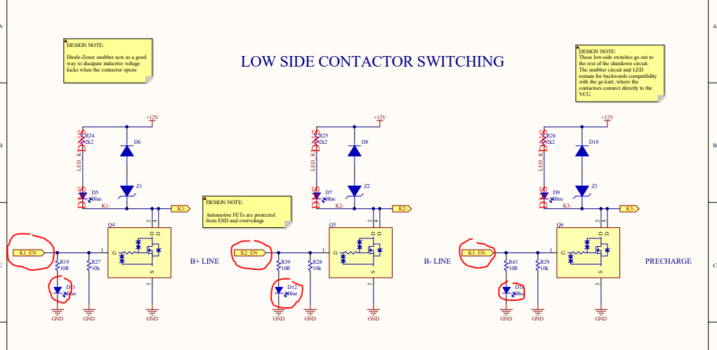
-
Note the label attached to each one: K1_EN, K2_EN, K3_EN. These are important to make the connection with the microcontroller pins.
-
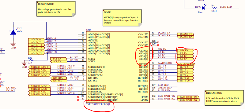
Check out page 4. The big yellow rectangle in the middle represents the TMS570 microcontroller. On the right you can see that the K1_EN, K2_EN, and K3_EN pins are connected to some GIO pins on the TMS570.
- Using this information, blink the LEDs the same way you would in Project 0. (Halcogen initialization & CCS code)
NOTE: When creating the Halcogen project, make sure to select the TMS570LS1227PGE. When creating the CCS project, make sure you select the SEGGER J-Link Emulator as the Connection, and the TMS570LS1227 as the Device.
- Try out different LED patterns, check out how the pin numbers correlate to the order of the LEDs on the physical circuit board.
The VCU has an RGB status LED. It's useful to indicate the current state of the VCU. The RGB LED is connected to three different MCU pins, one for Red, one for Green, and one for Blue.
-
Examine page 4 of the schematic. Note that one side of each LED is connected to 3.3V. We control the bottom side voltage after the resistor.
-
Note that the LEDs are connected to the HET pins of the microcontroller, these require slightly different code than pins connected to GIO modules. Luckily the HET pins can act as digital inputs and outputs as well.
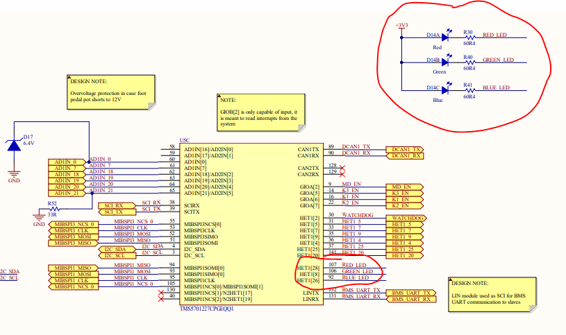
Red LED - HET1[28]
Green LED - HET1[8]
Blue LED - HET1[26]
NOTE: The logic for the signals is inverted for these 3 HET signals (HET1_28, HET1_8, HET1_26) on the LEDs (all other HET pins operate normally). When 3.3V is sent from the MCU pins, the LED has no potential difference across it and current will not flow to turn it on. When 0V is sent from the MCU pins, the LED current will flow and turn on.
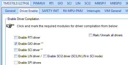
- To use the HET pins as GPIOs, you only need to enable the GIO driver. Enable it in Halcogen.
-
While gioInit() is used to initialize all the GIO pins normally, the HET pins need to be initialized by using the GIO APIs.
-
Make sure to #include "gio.h" and "het.h"
-
Set all the HET pins to GPIO outputs by using
gioSetDirection(hetPORT1, 0xFFFFFFFF);Note the hetPORT1 instead of gioPORTA for example. -
If you'd like you can set more parameters for the HET pins: pull-up/pull-down, open drain, push-pull etc.. For this tutorial we only need to set the direction to output as done in the last step.
-
Turn OFF the three LEDs by using the GIO API function gioSetBit().
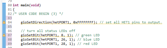
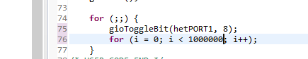
- Toggle the green LED by using
gioToggleBit(hetPORT1, 8);
Use your favourite method for blinking an LED. One option is to use timers, another is to put the LED blinking in freeRTOS tasks. Here we'll just put a basic busy wait delay.
- Blink the red and blue LEDs. Create cool patterns!