Unboxing and Setup
Welcome to working with our Vehicle Control Unit! The VCU is the main control unit in the car. The same circuit board is used for the BMS Master, so if you are on the BMS team all the same VCU tutorials and setup apply to you as well. From here on out we'll refer to the circuit board as the VCU.
--> pic of everything in the box
- Open up your VCU box, it should contain the following:
- 1 VCU
- 1 J-link Segger
- 1 20-pin to 10-pin adapter (should already be plugged into the J-link)
- 1 10-pin ribbon cable (should already be plugged into the adapter)
- 1 USB type B to USB type A cable
- 1 USB type A to micro USB cable
- Plug the type-B cable into the J-link. If the 10-pin ribbon connector or adapter are not already attached, please connect them as shown below:
--> pic of how to plug in the adapter and ribbon cable
- Carefully plug the ribbon connector into the VCU JTAG connector. Carefully plug the micro USB cable into the VCU connector.
--> pic of cables connected to VCU
Note: NEVER use the VCU on an exposed metal table. The pins and pads on the bottom of the circuit board are very capable of shorting and placing the VCU on a metal table could short the circuit board and damage components. Place the VCU on an insulated surface (plastic, wood, cloth, ESD bag, etc..).
Note: Please handle the board carefully, hold it only from the edges and avoid touching components if possible. ElectroStatic Discharge (ESD) is a board killer, good practice is to ground yourself as often as possible.
Okay on to the fun stuff!
- Plug the J-link and the micro-USB cables into your computer. The USB cable provides 5V power to the VCU. Two LEDs near the top of the board should turn on, they indicate 5V and 3.3V are both active.
If these LEDs do not light up, double check your cable connection and USB port. If the port and cable work properly with other devices, please disconnect the VCU from the PC immediately and inform your Embedded Lead.
--> pic of VCU on with LEDs
The J-link is a debugger and is used to flash code onto our microcontroller and debug it. Debugging means we can step line by line when we run the code, view the mcu registers and variable values live, and stop at breakpoints we set.
To be able to use the J-Link debugger in Code Composer, you'll need to add the debugger to CCS. If you don't see the SEGGER J-Link Emulator in your project connection, install the driver below.
- Adding J-Link to CCS as a debugger - Needed to use the J-link to debug any of the VCUs in Code Composer Studio
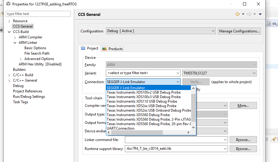
- Open up a pre-existing project. Make sure your target connection is set to the TMS570LS1227 as shown above.
- Debug the project. A pop-up window should appear mentioning the educational nature of the J-Link EDU. Click 'Do not show this message again today' and accept the terms.
- Press play, and try out debugging features. Make sure the J-Link is able to stop, resume, and halt at breakpoints in the code.
The micro USB cable connected to the VCU creates a serial connection with your computer.
- Verify that this connection is active by checking your Device Manager. A new device COM port should appear when the VCU is plugged in. This is what we'll use when we are sending data via the SCI to a serial port on the PC.
--> pic
If working with Mac or Linux, list all the connected USB devices by typing ioreg -p IOUSB into the terminal. It should list everything connected. The terminal should look as shown below.
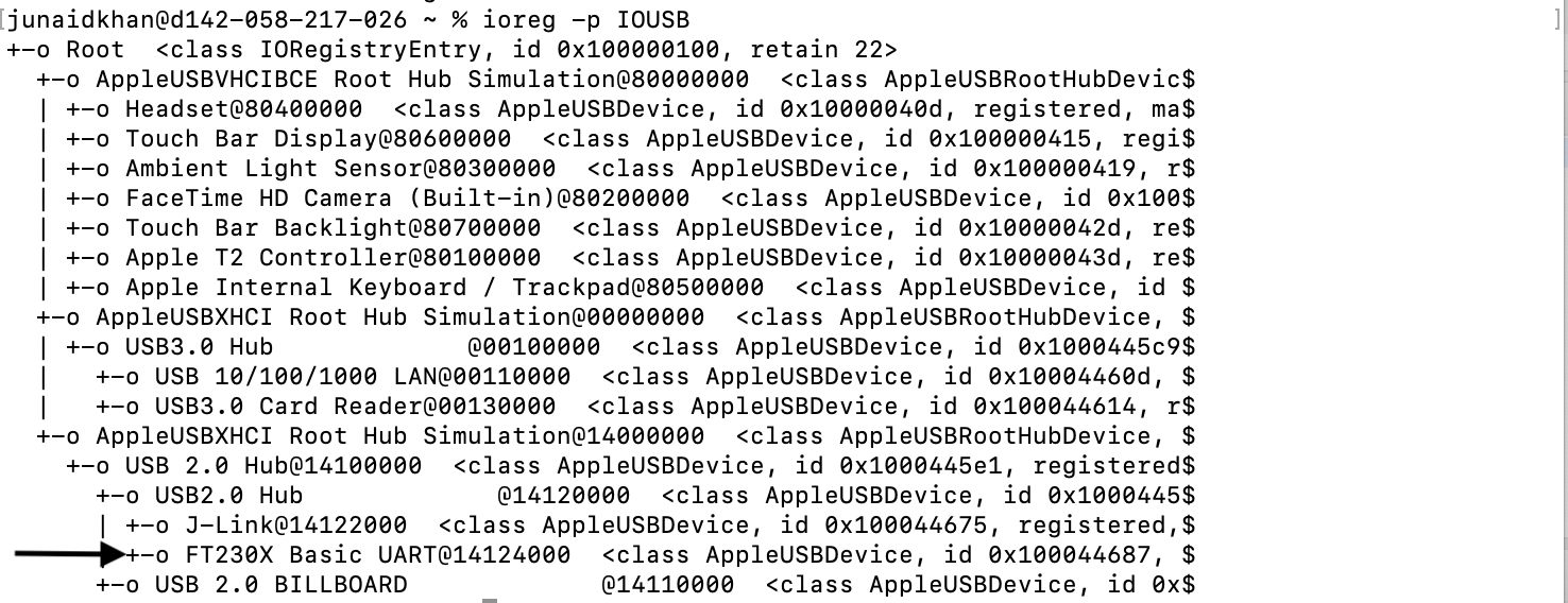
From the image above, the arrow shows a USB connection below the J-Link connection. To confirm if this is the COM port of the VCU, go to:
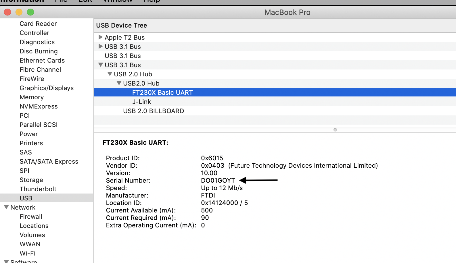
About This Mac -> System Report -> USB (under Hardware)-> Look for 'USB2.0 Hub' in the USB device tree
Next,
Select 'FT230X Basic UART' and look for the 'Serial Number', keep this window open - shown below:
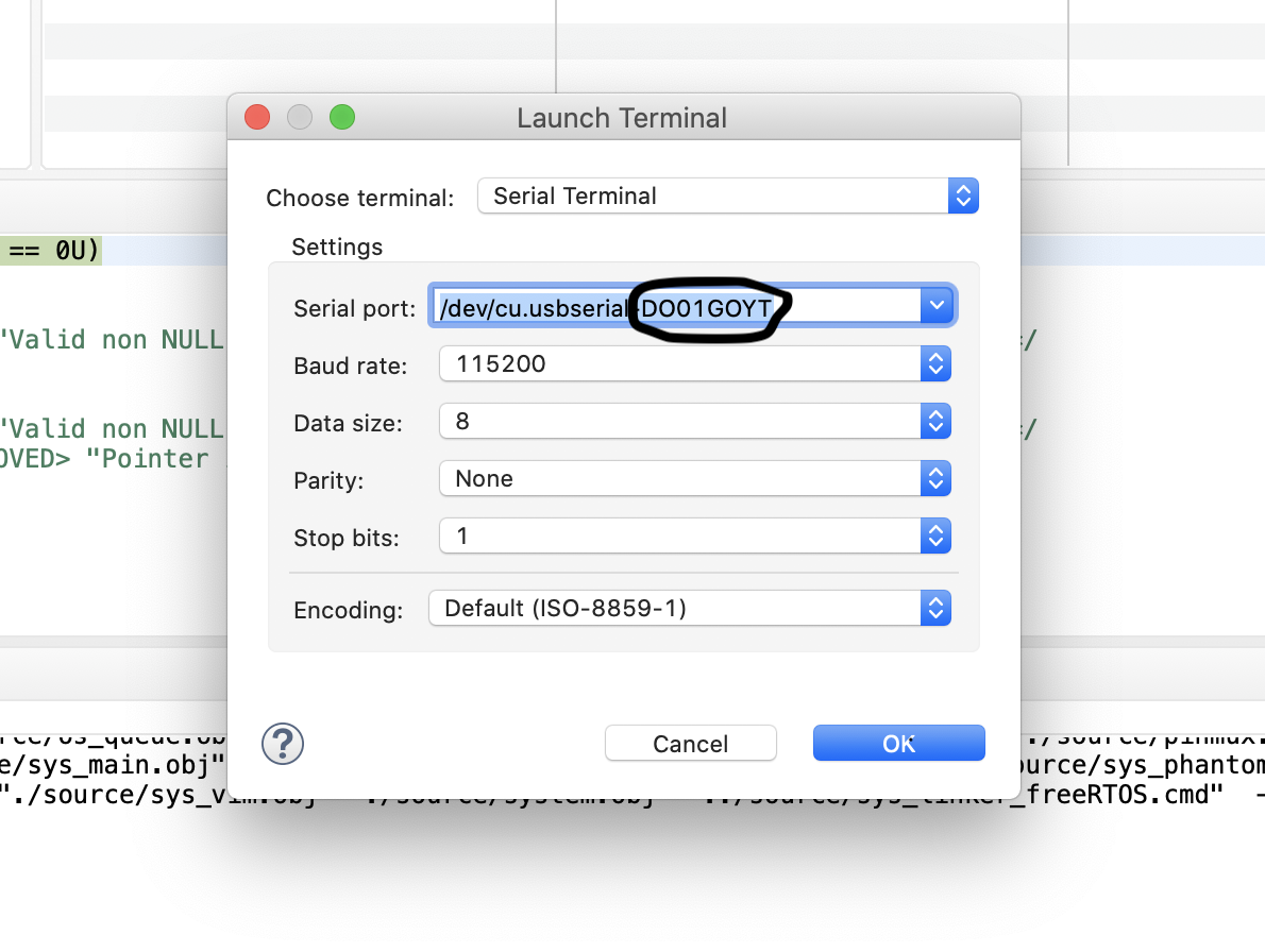
Next, open CCS Terminal and look for the 'Serial Port' that has the name as the 'Serial Number' from the previous step - shown below:
--> pic
- If the COM port (or serial device) does not appear, try unplugging and re-plugging in the VCU. If the COM port still does not appear, you may be missing the right driver.
- Install the FTDI Virtual COM Port (VCP) drivers for your specific operating system (Windows, Linux, Mac). They enable the FTDI chip on the VCU to be recognized by your computer.
--> pic of driver 4. Unplug and replug in the VCU. A new serial device should now show up. If nothing continues to happen, switch your micro USB cable, some of them are not capable of sending data.
Should the device continue to not connect successfully, please contact your Embedded Lead.